
HMT (head-mounted display) optical system provided with adjustable exit pupil

An optical system and display technology, applied in optics, optical components, instruments, etc., can solve the problems of complex structure, complex processing technology, and the inability to realize arbitrary adjustment of the exit pupil, so as to avoid the change of the overall structure, reduce the difficulty of processing and assembly, The effect of improving the utilization rate of light energy

Pending Publication Date: 2017-05-31
TAPUYIHAI SHANGHAI INTELLIGENT TECH CO LTD
View PDF5 Cites 8 Cited by
  • Summary
  • Abstract
  • Description
  • Claims
  • Application Information

AI Technical Summary

Problems solved by technology

[0005] 1) The processing of diffractive optical elements or microlens arrays is difficult, the processing technology is complicated, and the cost is high;
[0006] 2) Stray light and dispersion caused by diffraction are difficult to correct through the optical system, which reduces the imaging quality of HMD;
[0007] 3) The surface shape error caused by the processing technology and the interference between each diffraction order reduce the uniformity of illumination of the exit pupil surface of the HMD;
[0008] 4) The diffraction efficiency of the diffraction grating affects the light energy utilization rate of the HMD and reduces the brightness of the exit pupil surface of the HMD;
[0009] 5) The use of the exit pupil expander increases the difficulty of assembling the HMD and makes its structure complex;
[0010] 6) The exit pupil expander of the HMD can only expand the exit pupil to a fixed value, and cannot achieve arbitrary adjustment of the exit pupil

Method used


Image

  • HMT (head-mounted display) optical system provided with adjustable exit pupil
  • HMT (head-mounted display) optical system provided with adjustable exit pupil
  • HMT (head-mounted display) optical system provided with adjustable exit pupil

Examples


Embodiment Construction

[0030] The present invention will be described in detail below in conjunction with specific embodiments and accompanying drawings.

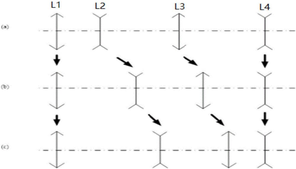
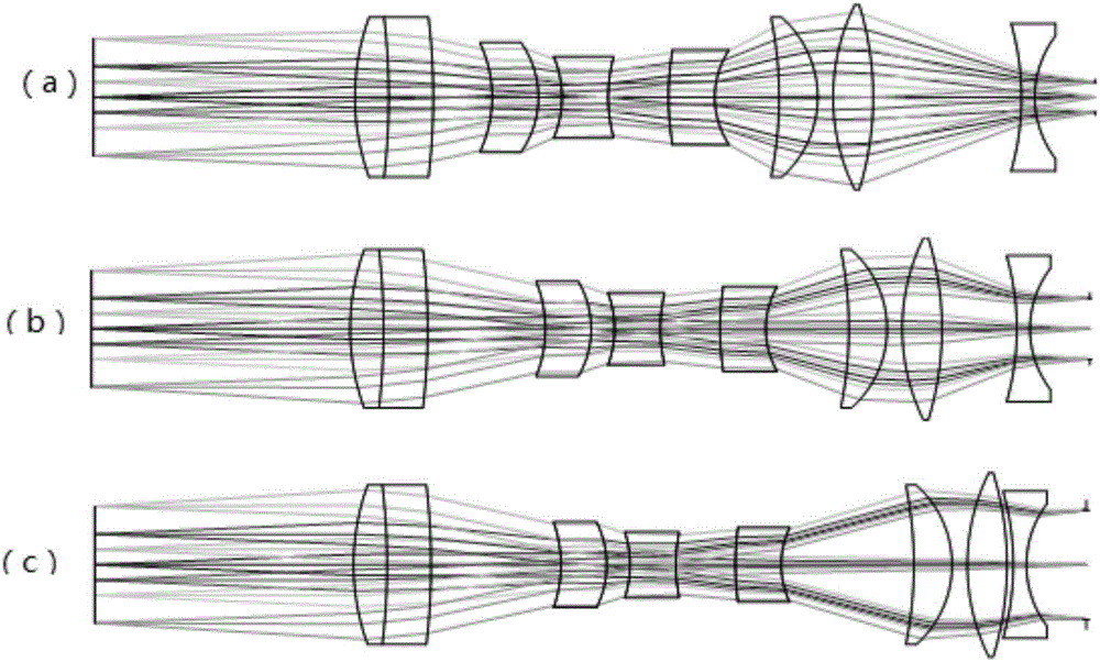
[0031] The head-mounted display optical system with adjustable exit pupil of the present invention is as figure 2 shown. It can be seen from the figure that the optical system of the head-mounted display with adjustable exit pupil of the present invention is composed of the front fixed group L1, the zoom group L2, the compensation group L3 and the rear fixed group L4. On the surface, there are the front fixed group L1, zoom group L2, compensation group L3 and rear fixed group L4 in sequence, and the front fixed group, zoom group, compensation group and rear fixed group are placed axisymmetrically with respect to the optical axis, The front fixed group and the rear fixed group keep their positions unchanged during the zooming process of the optical system, and the zooming group and compensation group move along the optical axis according to thei...


PUM


Abstract

An HMT (head-mounted display) optical system provided with an adjustable exit pupil comprises a front fixing group, a zooming group, a compensation group and a rear fixing group. The position relation is shown as follows: with a microdisplay or a middle image plane as an object plane, the front fixing group, the zooming group, the compensation group and the rear fixing group are arranged sequentially, and each of the front fixing group, the zooming group, the compensation group and the rear fixing group is arranged in an axial symmetry manner relative to an optical axis; the front fixing group and the rear fixing group always keep unchanged in position in the zooming process of the optical system, and the zooming group and the compensation group move along the optical axis in accordance with respective curves in the zooming process of the optical system. A front focal plane and a rear focal plane of the optical system are kept fixed in the moving process of the zooming group and the compensation group, so that the front focal plane of the optical system and the object plane coincide, and the rear focal plane of the optical system and the exit pupil coincide. The optical system has the characteristics of being simple in structure, high in light energy utilization rate, high in imaging quality and the like and can realize expansion and intelligent adjustment of the exit pupil.

Description

technical field [0001] The present invention relates to head-mounted displays. In particular, a head-mounted display optical system with an adjustable exit pupil. Background technique [0002] A typical head-mounted display (hereinafter referred to as HMD) consists of two parts: a microdisplay and an optical system. As a visual optical system, the exit pupil of the HMD coincides with the pupil of the human eye. In order to effectively cooperate with human vision to achieve the best display effect and realize the effective use of incident light energy, the design of HMD must fully consider the brightness of the microdisplay, the field of view of the optical system, the exit pupil parameters and the imaging quality. Among them, the exit pupil parameter is one of the important design parameters of the optical system, which mainly includes exit pupil diameter, exit pupil distance and exit pupil distance. Under the premise of satisfying the exit pupil distance and the strict m...

Claims


Application Information

Patent Timeline
IPC IPC(8): G02B27/01
CPCG02B27/0172
Inventor 方瑞芳
Owner TAPUYIHAI SHANGHAI INTELLIGENT TECH CO LTD
Learn More