Guide device, landmark layout method and guide method based on multi-view vision and inertial navigation

A multi-eye vision and guidance device technology, applied in the field of guidance devices based on multi-eye vision and inertial navigation, can solve problems such as poor operation reliability, low positioning accuracy, and poor navigation flexibility

Active Publication Date: 2017-05-31
NANJING UNIV OF AERONAUTICS & ASTRONAUTICS
View PDF9 Cites 57 Cited by
  • Summary
  • Abstract
  • Description
  • Claims
  • Application Information

AI Technical Summary

Problems solved by technology

[0008] Aiming at the deficiencies of the above-mentioned prior art, the purpose of the present invention is to provide a guidance device, landmark layout and guidance method based on multi-eye vision and inertial navigation, so as to solve the shortcomings of various guidance technologies in the prior art. , there are problems such as poor navigation flexibility, low positioning accuracy, and poor operational reliability.

Method used


Image

  • Guide device, landmark layout method and guide method based on multi-view vision and inertial navigation
  • Guide device, landmark layout method and guide method based on multi-view vision and inertial navigation
  • Guide device, landmark layout method and guide method based on multi-view vision and inertial navigation

Examples


Embodiment Construction

[0060] In order to facilitate the understanding of those skilled in the art, the present invention will be further described below in conjunction with the embodiments and accompanying drawings, and the contents mentioned in the embodiments are not intended to limit the present invention.

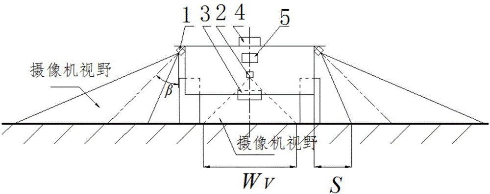
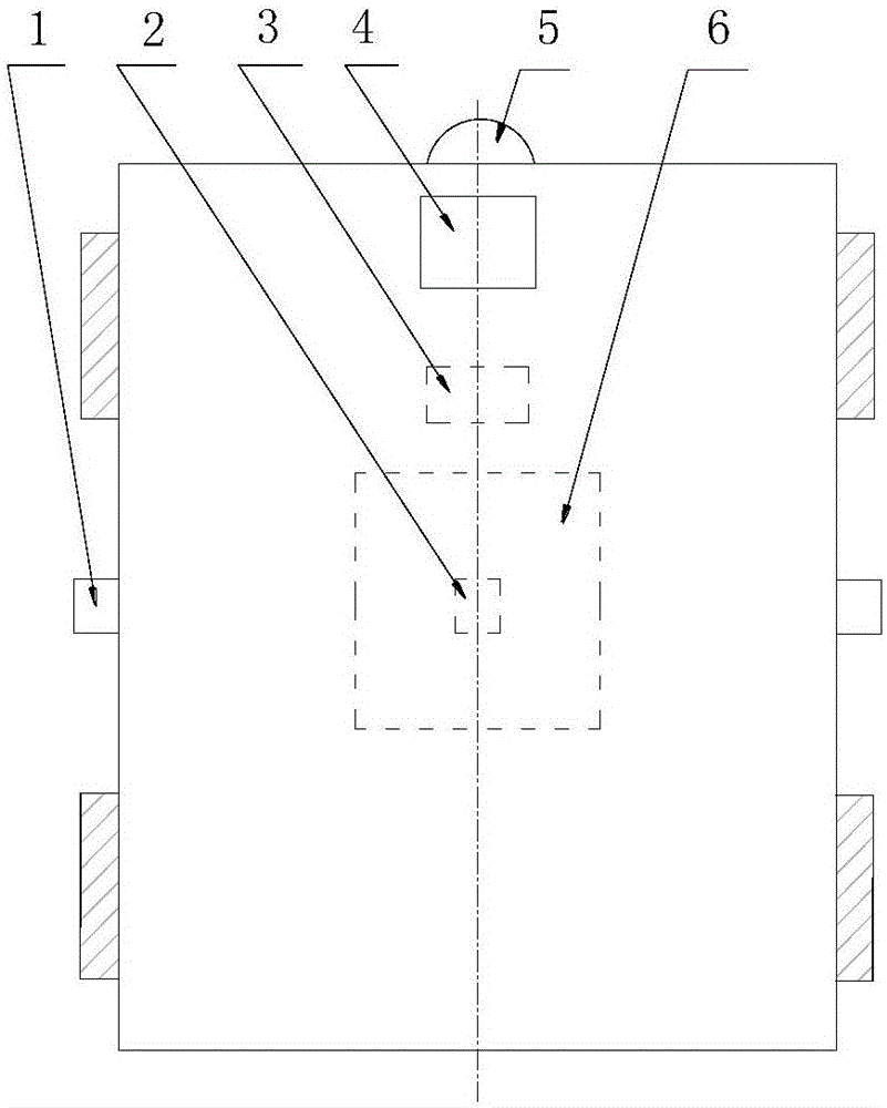
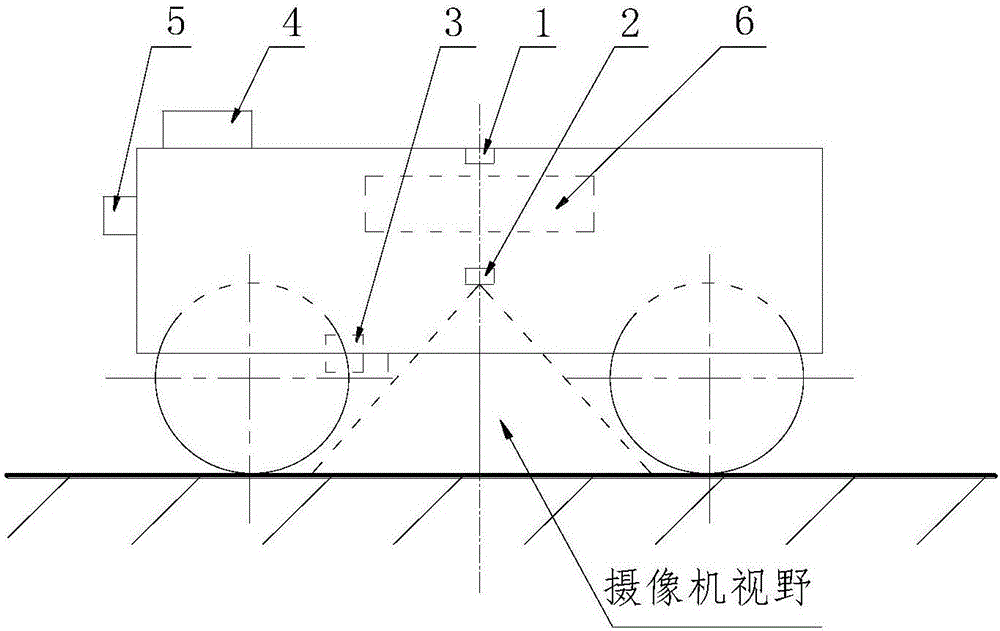
[0061] refer to Figure 1 to Figure 3 As shown, the guidance device based on multi-eye vision and inertial navigation of the present invention includes: side camera 1, center camera 2, radio frequency card reader 3, inertial measurement unit 4, obstacle sensor 5, guidance controller 6 Wherein, the lateral camera 1 is installed obliquely downward on the left and right sides of the car body (that is, the car body of the automatic guided vehicle); the center camera 2 is installed vertically downward on the central axis of the car body, and the left and right boundaries of its field of view are in line with the The lateral boundaries of the vehicle body are parallel, and the field of view width ...


PUM


Abstract

The invention discloses a guide device, a landmark layout method and a guide method based on multi-view vision and inertial navigation, belonging to the automatic control field. The guide device comprises oblique-downward cameras, a vertical-downward camera, an inertial measurement unit, a barrier sensor, a radio frequency card reader and a guide controller, wherein the oblique-downward cameras are arranged on two sides of a vehicle body, the vertical-downward camera is arranged at the center of the vehicle body, the inertial measurement unit is arranged on the top of the vehicle body, the barrier sensor is arranged on the front side of the vehicle body, the radio frequency card reader is arranged at the bottom of the vehicle body, and the guide controller is electrically connected with the cameras, the inertial measurement unit, the barrier sensor and the radio frequency card reader. Color guiding marked lines are distributed on two sides of an operation path of an automatic guide vehicle (AGV), and radio frequency tags and colored positioning marks which are in positional coincident with each other are distributed on the guiding marked lines. A guide method of the AGV comprises the steps of carrying out region traffic navigation in a middle region between the guiding marked lines on two sides, and carrying out path tracking guide along with the guiding marked lines on one side. The guide method has cross-regional remote motion flexibility and intra-regional target positioning accuracy.

Description

technical field [0001] The invention belongs to the technical field of mobile robot navigation in automation control, and specifically refers to a guidance device, landmark layout and guidance method based on multi-eye vision and inertial navigation. Background technique [0002] The research on automatic guided technology began in the United States in the 1950s. In 1954, Barret Electronics developed the first automatic guided vehicle for cargo delivery, and then the application of automatic guided vehicles was extended to the field of industrial production. In 1974, the Volvo Kalmar car assembly plant in Sweden adopted automatic guided vehicles as the carrier of the automatic assembly line. Since the 1980s, the U.S. Department of Defense has started research on ground unmanned combat platforms, mainly targeting intelligent vehicles that adapt to different terrains and autonomously navigate. [0003] Automatic guidance technology has always been the core technology in the f...

Claims


Application Information

Patent Timeline
Patent Type & Authority Applications(China)
IPC IPC(8): G05D1/02
CPCG05D1/0231G05D1/027G05D1/028G05D1/0234G05D1/0289G05D2201/0216
Inventor 武星楼佩煌张颖张建鹏钱晓明金鹏陈华何珍
Owner NANJING UNIV OF AERONAUTICS & ASTRONAUTICS
Why Eureka
Try Eureka