A Lane Line Recognition Method for Expressway Sections and Urban Roads

A technology for lane line recognition and high-speed road sections, which is applied in the field of image processing, can solve problems such as difficult detection of lane lines, and achieve the effects of enhanced real-time performance, good real-time performance, and improved accuracy

Active Publication Date: 2020-07-31
NANJING UNIV OF SCI & TECH
View PDF4 Cites 0 Cited by
  • Summary
  • Abstract
  • Description
  • Claims
  • Application Information

AI Technical Summary

Problems solved by technology

[0005] The purpose of the present invention is to provide a lane line identification method for high-speed road sections and urban roads, which overcomes the problem that lane lines are difficult to detect under the interference of various factors, and has real-time performance

Method used


Image

  • A Lane Line Recognition Method for Expressway Sections and Urban Roads
  • A Lane Line Recognition Method for Expressway Sections and Urban Roads
  • A Lane Line Recognition Method for Expressway Sections and Urban Roads

Examples


Embodiment

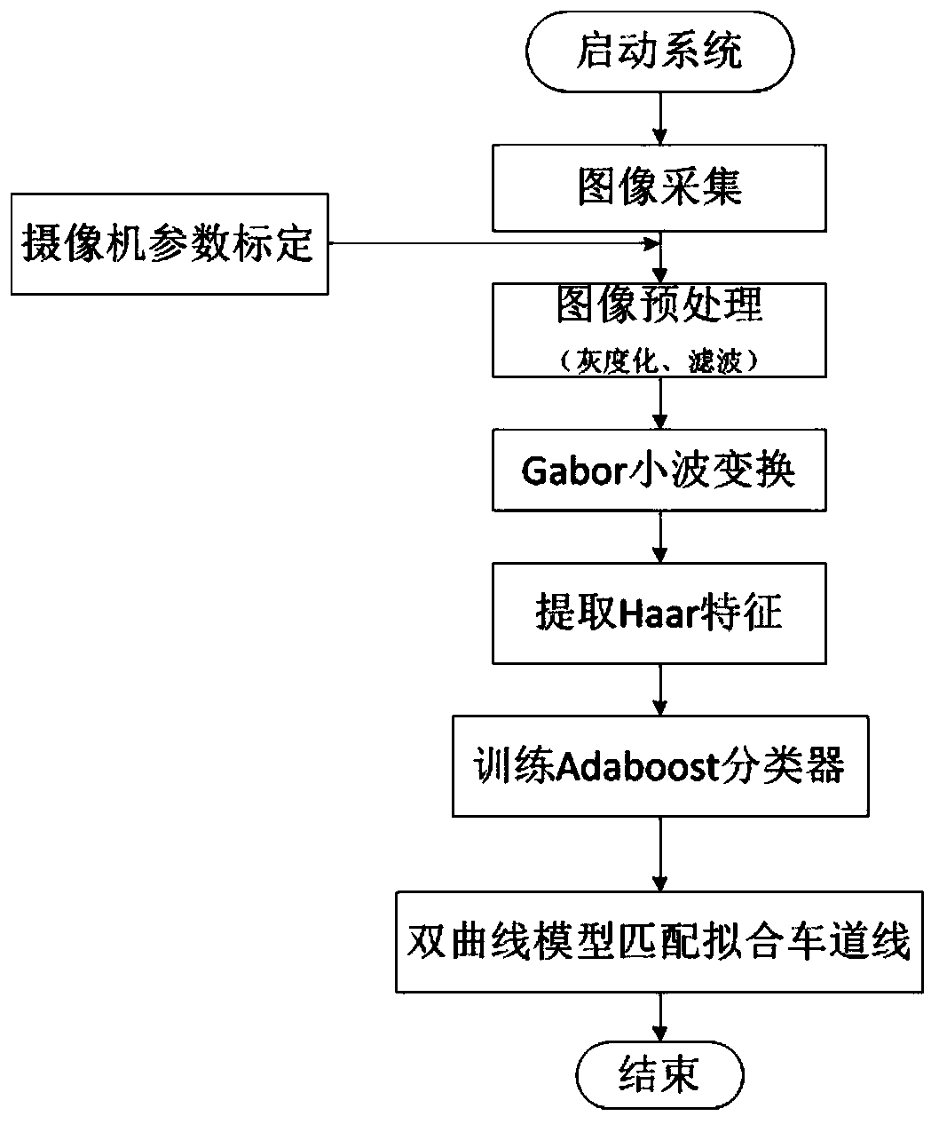
[0054] combine figure 1 , a highway segment and urban road lane line identification method, comprising the following steps:

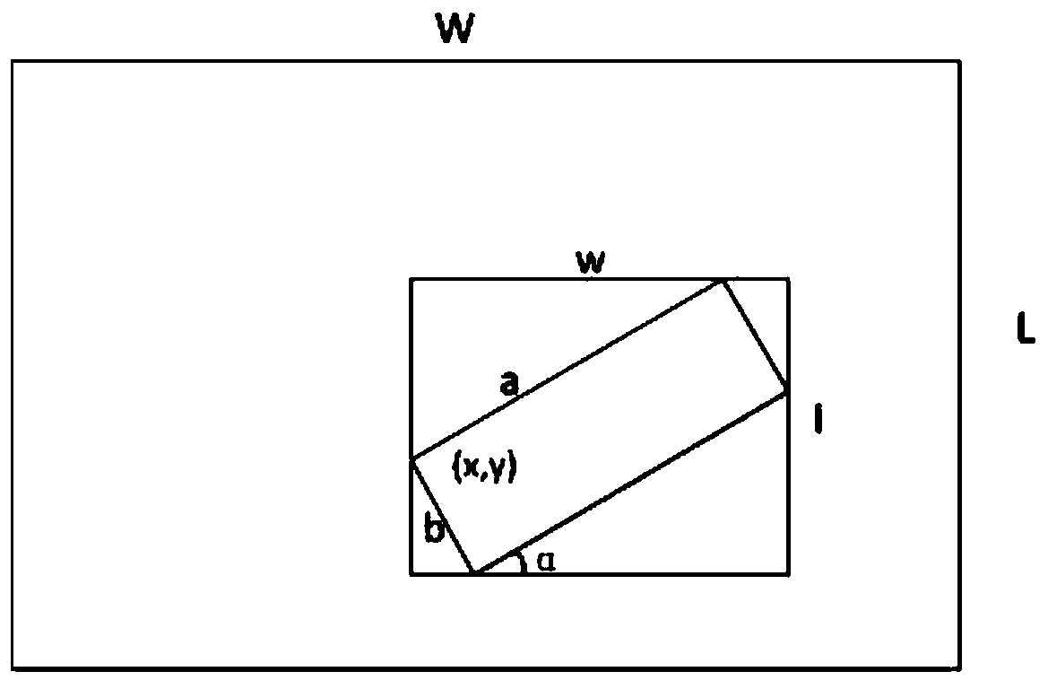
[0055] Step 1. Obtain the road image through the camera and calculate the relevant parameters

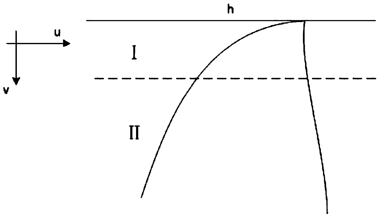
[0056] The image coordinates obtained by the camera are (u, v), and the mapping coordinates on the road surface coordinate system are (x, y). The camera is placed at a height h from the ground, and the deflection angle is Let the coordinates of point P in the road surface coordinate system be [x, y, z] T , while the coordinates of point P in the image coordinate system are [wu,wv,w] T , the corresponding relationship is where K is the camera calibration matrix, R is the rotation matrix, I is the identity matrix, [I 3×3|-T] is the concatenation of I and T, T=[0,0,h] T , the z coordinate of the road surface in the road surface coordinate system is 0, (u c ,v c ) is the principal point position of the image coordinate plane, and f is the effective f...


PUM


Abstract

The invention discloses a lane line recognition method for highway sections and urban roads, which comprises the following steps: acquiring lane images through a camera, using a camera parameter self-calibration method to obtain internal and external parameters of the camera, and obtaining lane plane vanishing lines; graying out the lane images Degree-based processing and division of interest areas; Median filtering is performed on the image obtained in the previous step; Gabor transform is used to extract lane line texture features on the median-filtered image; Multi-angle Haar features are used to describe lane line edge features, and Adaboost classification is used Classification and identification are carried out by the controller; the hyperbolic combination model is designed for structured roads; the parameters of the hyperbolic combination model are estimated by the improved Ransac algorithm. The invention solves the problem of lane line detection in complex environments such as shadows, lane line wear and bad weather, and has good real-time performance.

Description

technical field [0001] The invention belongs to the technical field of image processing, and in particular relates to a lane line recognition method for highway sections and urban roads. Background technique [0002] Lane recognition is a core part of advanced driver assistance systems. Due to the low cost of vision sensors and the ease of system construction, machine vision-based lane line detection methods are widely used. The lane detection methods based on machine vision can generally be divided into two categories: methods based on image features and methods based on model recognition. [0003] The method based on image features is mainly to recognize the gray edge in the gray image, while the method based on the model is to establish a mathematical model to represent the boundary of the lane. Model-based recognition methods are usually used on urban streets and highways. Commonly used lane line detection models include straight line models, hyperbolic models, parabol...

Claims


Application Information

Patent Timeline
Patent Type & Authority Patents(China)
IPC IPC(8): G06K9/00
CPCG06V20/588
Inventor 成剑沙涛
Owner NANJING UNIV OF SCI & TECH
Why Eureka
Try Eureka