Three-cooling type fuel rod and fuel assembly

A fuel rod and cold type technology, applied in the direction of fuel elements, greenhouse gas reduction, nuclear power generation, etc., can solve the problem of insufficient and effective absorption of thermal neutrons, reduction of reactor core economy, radial thermal expansion of large pellets, etc. problem, achieve the effect of reducing self-screening effect, reducing the probability of PCMI failure, and long cycle length

Active Publication Date: 2017-05-31
CHINA NUCLEAR POWER TECH RES INST CO LTD +2
View PDF4 Cites 5 Cited by
  • Summary
  • Abstract
  • Description
  • Claims
  • Application Information

AI Technical Summary

Problems solved by technology

For solid pellets, after thermal neutrons enter the fuel rod, they are first absorbed by the fissile material in the outer layer of the pellet, resulting in a lower thermal neutron flux density inside the pellet than in the outer layer, resulting in fission in the inner layer of the pellet The material cannot absorb thermal neutrons sufficiently efficiently
That is to say, the fissile material in the outer layer has a shielding effect on the fissile material in the inner layer, which is the self-shielding effect, and the self-shielding effect will cause the core block to be radially inward, the more fissile material remains, and it is easy to cause fission Waste of resources, reducing the economics of the reactor core
[0003] If an accident like RIA (Reactivity Introduced Accident) occurs in a nuclear reactor, because the solid pellet has a large radial thickness, it will produce a large radial thermal expansion of the pellet, so that the fuel rod is more prone to PCMI (pellet Mechanical interaction with cladding) failure
In addition, a larger pellet radius will cause the core temperature of the pellet to be too high, which is prone to pellet melting

Method used


Image

  • Three-cooling type fuel rod and fuel assembly
  • Three-cooling type fuel rod and fuel assembly
  • Three-cooling type fuel rod and fuel assembly

Examples


Embodiment Construction

[0024] In order to have a clearer understanding of the technical features, purposes and effects of the present invention, the specific implementation manners of the present invention will now be described in detail with reference to the accompanying drawings.

[0025] The three-cooled fuel rod of the first embodiment of the present invention is used for nuclear reactor fuel assembly. The three-cooled fuel rod includes a rod body.

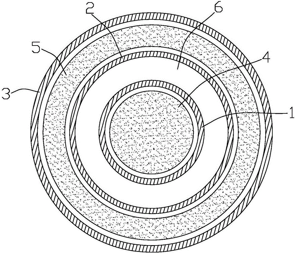
[0026] Such as figure 1 As shown, the rod body includes an inner shell 1, a middle shell 2 and an outer shell 3 that are sequentially sleeved outside the inner shell 1; and also includes a first core block 4 arranged inside the inner shell 1 And the second core block 5 arranged between the middle cladding 2 and the outer cladding 3 . The middle cladding 2 is separated from the inner cladding 1 , and the annular space between the two forms an internal cooling passage 6 through which the coolant passes. The circulation of coolant such as water in t...


PUM


Abstract

The invention discloses a three-cooling type fuel rod and a fuel assembly. The three-cooling type fuel rod comprises a rod body, wherein the rod body comprises an inner cladding, a middle cladding, an outer cladding, a first pellet and a second pellet; the middle cladding and the outer cladding are sequentially sheathed on the exterior of the inner cladding; the first pellet is arranged in the inner cladding, and the second pellet is arranged between the middle cladding and the outer cladding; an annular gap between the middle cladding and the outer cladding forms an inner cooling passage for a coolant to pass through. Compared with the solid pellet in the prior art, the three-cooling type fuel rod has the advantages that by arranging multiple claddings and the inner pellet, at the premise of same reactor core uranium charging amount, the radial thickness of the pellet is greatly reduced, so that the self-shield effect is obviously reduced, and the remaining amount of crackable material is reduced; the radial thickness of the pellet is greatly reduced, the radial expansion amount of the pellet is also reduced, the PCMI (pellet and cladding mechanical interaction) load under the special accident condition of a reactor is reduced, and the probability of PCMI failure of the fuel rod is further reduced.

Description

technical field [0001] The invention relates to a nuclear fuel rod, in particular to a triple-cooled fuel rod and a fuel assembly using the nuclear fuel rod. Background technique [0002] The core of the pressurized water reactor nuclear power plant is composed of multiple fuel assemblies. Among the existing fuel assemblies, the pellets of the fuel rods are mostly solid. For solid pellets, after thermal neutrons enter the fuel rod, they are first absorbed by the fissile material in the outer layer of the pellet, resulting in a lower thermal neutron flux density inside the pellet than in the outer layer, resulting in fission in the inner layer of the pellet The material cannot absorb thermal neutrons sufficiently efficiently. That is to say, the fissile material in the outer layer has a shielding effect on the fissile material in the inner layer, which is the self-shielding effect, and the self-shielding effect will cause the core block to be radially inward, the more fissil...

Claims


Application Information

Patent Timeline
Patent Type & Authority Applications(China)
IPC IPC(8): G21C3/06
CPCG21C3/06Y02E30/30
Inventor 卢志威刘彤任啟森李雷严岩李云张显生武海龙肖玲
Owner CHINA NUCLEAR POWER TECH RES INST CO LTD
Why Eureka
Try Eureka