Oil damping hydraulic electromagnetic releasing mechanism and high-current circuit breaker with same

A technology of tripping mechanism and oil damper, applied in the direction of protection switch operation/release mechanism, etc., can solve the problems of unusable and direct winding, etc., and achieve the effect of easy processing and assembly and simple structure

Inactive Publication Date: 2017-05-31
张文红 +1
View PDF5 Cites 0 Cited by
  • Summary
  • Abstract
  • Description
  • Claims
  • Application Information

AI Technical Summary

Problems solved by technology

The traditional current coil design adopts the helical straight-wound method, but this kind of helical direct-wound current coil can only be used in the oil-damped hydraulic electromagnetic tripping mechanism of low-current low-voltage circuit breakers, and cannot be used in the rated current. In the oil damping hydraulic electromagnetic tripping mechanism of a large current circuit breaker, the reason is that in the tripping system space of the low-voltage circuit breaker, the square of the current conductive busbar of its main circuit must be satisfied. 2 If calculated by the current of 3.5A, assuming that the rated current of the low-voltage circuit breaker is 630A, the cross-sectional area of ​​the conductive busbar needs to be 180mm 2
From a technical point of view, it is impossible to achieve such a small coil diameter on the busbar of such a large conductive circuit by direct winding.

Method used


Image

  • Oil damping hydraulic electromagnetic releasing mechanism and high-current circuit breaker with same
  • Oil damping hydraulic electromagnetic releasing mechanism and high-current circuit breaker with same
  • Oil damping hydraulic electromagnetic releasing mechanism and high-current circuit breaker with same

Examples


Embodiment 1

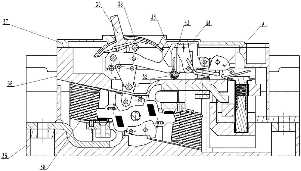
[0040] One embodiment of the present invention is a low-voltage molded case circuit breaker, which is a double-breakpoint circuit breaker with relatively large rated current, including a main circuit unit, an operating mechanism and an oil damping hydraulic electromagnetic tripping mechanism, and is also equipped with An electromagnetic tripping mechanism connected with the operating mechanism and a mechanical amplifying transmission mechanism arranged between the operating mechanism and the oil damping hydraulic electromagnetic tripping mechanism. In addition to the above-mentioned main components, the circuit breaker also includes components such as a base 35, a middle base 36, a cover 37, an arc extinguishing chamber 38 and corresponding fasteners.

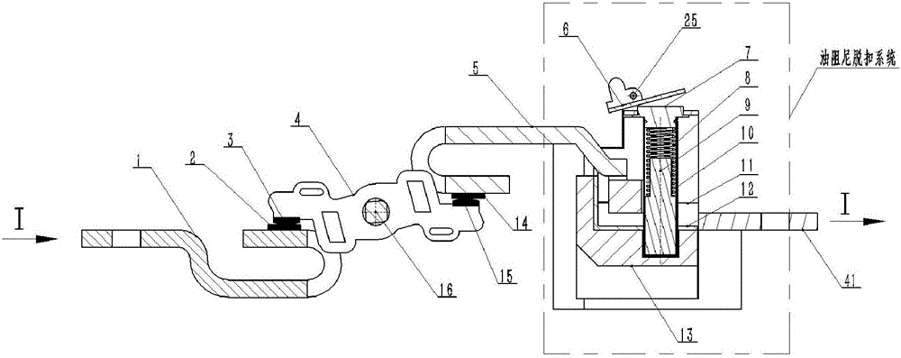
[0041] like image 3 As shown, the main circuit unit is mainly composed of the first static conductive bridge 1, the first static contact 2, the first movable contact 3, the movable conductive bridge 4, the second movable conta...


PUM


Abstract

The invention discloses an oil damping hydraulic electromagnetic releasing mechanism and a high-current circuit breaker with the same, and belongs to the technical field of low-voltage circuit breakers. A current coil of the oil damping hydraulic electromagnetic releasing mechanism comprises a first U-shaped copper module, a second copper module and a third U-shaped copper module which are sequentially stacked on one another in the up-down direction, the first U-shaped copper module and the third U-shaped copper module are of U-shaped opening structures, two U-shaped openings are oppositely formed, the second copper module is arranged between the first U-shaped copper module and the third U-shaped copper module, an oil damper barrel is arranged between the U-shaped openings of the first U-shaped copper module and the third U-shaped copper module, and the first U-shaped copper module and the third U-shaped copper module are respectively connected with a main circuit unit of the circuit breaker. The corresponding high-current circuit breaker comprises the main circuit unit, an operation mechanism and the oil damping hydraulic electromagnetic releasing mechanism. The oil damping hydraulic electromagnetic releasing mechanism and the high-current circuit breaker have the advantage that problems of existing oil damping hydraulic electromagnetic releasing systems applied to low-voltage circuit breakers with high rated currents can be effectively solved.

Description

technical field [0001] The invention belongs to the technical field of low-voltage circuit breakers, and mainly relates to a high-current circuit breaker with an oil damping hydraulic electromagnetic tripping mechanism. Background technique [0002] A circuit breaker refers to the current that can connect, carry and break the external circuit working under normal circuit conditions, and can also connect and carry a certain amount of current under the specified abnormal circuit conditions (typically in the form of overload and short circuit). A mechanical switch that breaks current in time and in an instant. [0003] A low-voltage circuit breaker is a type of circuit breaker, and its entire system generally includes a main circuit unit, a tripping mechanism, an operating mechanism, etc. Among them, the main circuit unit is connected with the external circuit, the operating mechanism is used to connect or disconnect the main circuit unit, and the tripping mechanism is respons...

Claims


Application Information

Patent Timeline
Patent Type & Authority Applications(China)
IPC IPC(8): H01H71/24
CPCH01H71/24
Inventor 张文红薛风雷
Owner 张文红
Why Eureka
Try Eureka