
Microstrip Isolator Bonding Fixture

A technology of isolator and microstrip, which is applied in the direction of waveguide devices, circuits, electrical components, etc., can solve the problem of consistency, production efficiency is difficult to meet the potential needs of microstrip isolators, and the consistency of microstrip isolators is limited. The accuracy of the joint position, the inability to achieve the consistency of the permanent magnet bonding, etc., achieve good stability and position consistency, easy processing, and prevent misalignment.

Active Publication Date: 2022-03-01
SOUTHWEST INST OF APPLIED MAGNETICS
View PDF0 Cites 0 Cited by
  • Summary
  • Abstract
  • Description
  • Claims
  • Application Information

AI Technical Summary

Problems solved by technology

[0008] The permanent magnet is bonded by hand, and the appropriate position of the microstrip substrate can be found by visual observation. After bonding and curing, it is difficult to find the position only by eyes. The position accuracy that can be achieved is ±0.35mm, and the bonding position cannot be guaranteed. Accuracy, and thus can not achieve the consistency of permanent magnet bonding;
[0009] 2. Low efficiency
[0010] Purely manual bonding of permanent magnets, in order to obtain better matching performance, it is necessary to constantly find the position of the substrate, through the performance test verification, after calculation, the average bonding time of each microstrip isolator per person takes 2-3 minutes, bonding Good products do not meet the requirements of the bonding position, and the qualified rate is only below 80%. Therefore, a lot of working time and material materials are wasted through pure manual operation, and the product consistency and production efficiency are difficult to meet micro Potential demand for isolator development;
[0011] That is to say, for a long time, the consistency of the performance of the microstrip isolator is limited by the accuracy of the bonding position of the permanent magnet. In order to obtain better performance, it often requires a lot of man-hours and repeated bonding to achieve

Method used


Image

  • Microstrip Isolator Bonding Fixture
  • Microstrip Isolator Bonding Fixture
  • Microstrip Isolator Bonding Fixture

Examples


Embodiment

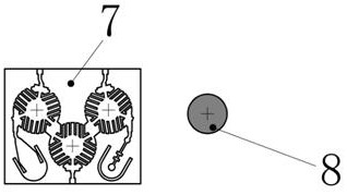
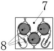
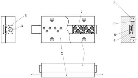
[0027] see Figure 3-7 , a bonding fixture for a microstrip isolator, comprising a microstrip substrate fixing module and a permanent magnet fixing module,

[0028] Wherein, the microstrip substrate fixed module, see Figure 4 with 5 , including a microstrip substrate 7, a substrate placement plate 1 for placing the microstrip substrate 7, a limiting block 5 and a locking screw 3 for limiting the microstrip substrate 7, and a positioning pin 6, limiting Block 5 is a polytetrafluoroethylene limit block;

[0029] During operation, put the microstrip substrate 7 into the chute 11 of the substrate placement plate 1 in the same direction, and prevent the microstrip substrate 7 from slipping out by rotating the polytetrafluoroethylene limit block 5 and the locking screw 3, and fix it well The relative position of the microstrip substrate 7 and the positioning pin 6 is a fixed value, which can better be docked with the permanent magnet fixed module;

[0030] The permanent magnet ...


PUM


Abstract

The invention discloses a bonding fixture for a microstrip isolator, which belongs to the field of microwave components and includes a microstrip substrate fixing module and a permanent magnet fixing module, wherein the microstrip substrate fixing module includes a microstrip substrate (7 ), a substrate placement plate (1), a limit block (5), a locking screw (3), and a positioning pin (6); the permanent magnet fixing module includes a permanent magnet placement block (2) and a permanent magnet (8 ), the permanent magnet placement block (2) is provided with a fixing groove (10) and a pin hole (9), the permanent magnet placement block (2) is also provided with an iron sheet (4), and the permanent magnet (8) is close to Iron sheet (4); the fixture of the present invention can significantly improve the position accuracy of permanent magnet bonding, and its accuracy can reach ±0.05mm, and has good stability and position consistency, and can be applied to various microstrips The isolator permanent magnet bonding process only takes 0.2‑0.3 minutes per person and per piece of microstrip isolator bonding, and the efficiency can be increased by more than 10 times.

Description

technical field [0001] The invention relates to the field of microwave components, in particular to a bonding fixture for a microstrip isolator. Background technique [0002] The microstrip isolator is one of the key devices in the microwave industry. It is installed between the power amplifier and the load. It can protect the power amplifier tube and improve the stability of the system by changing the propagation path of the reflected power caused by the mismatch of the load. [0003] With the development of modern wireless communication technology and the wide application of electronic systems, miniaturization and high performance have become an inevitable trend in the development of radio frequency microwave devices. With its own unique advantages, microstrip isolator technology is gradually becoming one of the key technologies for the miniaturization of the microwave industry. [0004] The microstrip isolator is mainly composed of a microstrip substrate and a permanent ...

Claims


Application Information

Patent Timeline
Patent Type & Authority Patents(China)
IPC IPC(8): H01P11/00H01P1/36
CPCH01P11/00H01P1/36
Inventor 丁敬垒
Owner SOUTHWEST INST OF APPLIED MAGNETICS
Learn More