Ultra-wideband ceiling antenna

A ceiling antenna and ultra-wideband technology, applied in the field of antennas, can solve the problem of scarcity of omnidirectional ceiling antennas, and achieve the effects of good roundness, changing antenna impedance and low cost

Active Publication Date: 2017-05-31
佛山市盛夫通信设备有限公司
View PDF3 Cites 0 Cited by
  • Summary
  • Abstract
  • Description
  • Claims
  • Application Information

AI Technical Summary

Problems solved by technology

However, omnidirectional ceiling antennas on the market that can cover all UHF frequency bands, meet the signal requirements of each frequency band, and have a simple structure and low manufacturing cost are very rare and in short supply.

Method used


Image

  • Ultra-wideband ceiling antenna
  • Ultra-wideband ceiling antenna
  • Ultra-wideband ceiling antenna

Examples


Embodiment Construction

[0019] The technical solution will be described in detail below in conjunction with specific embodiments.

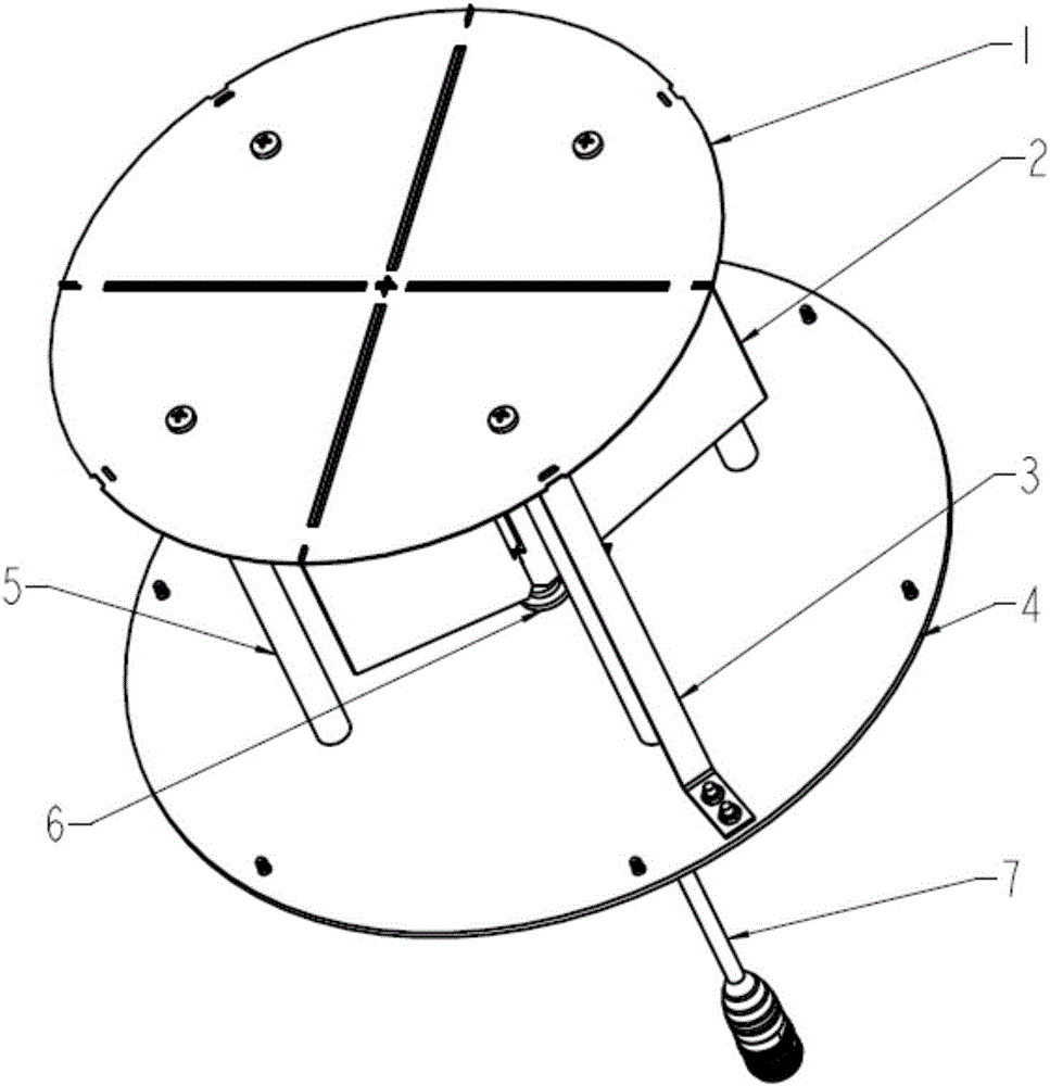
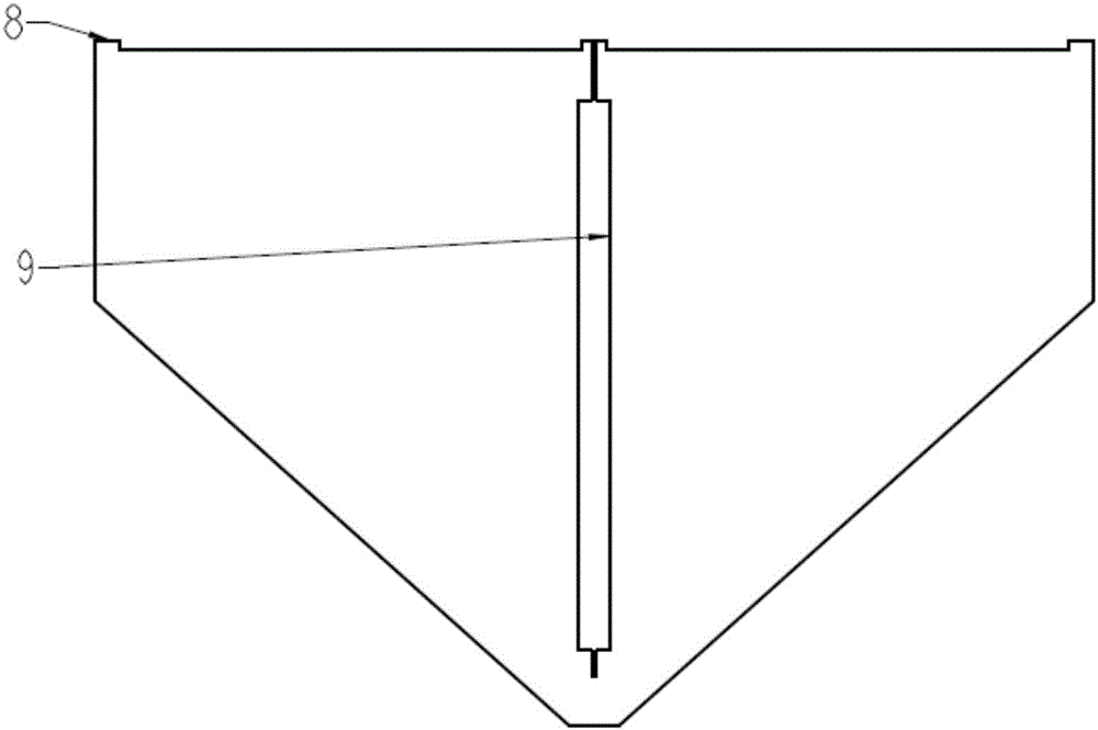
[0020] Such as Figure 1-Figure 4 As shown, the present invention is an ultra-wideband ceiling antenna, which is an ultra-wideband ceiling antenna applied to UHF / UWB. It includes a loading disc 1, a radiator 2, and a base plate 4, and a The ground sheet 3 and the support column 5, the support column is a non-metallic support cylinder. The feeder cable 7 passes through the bottom plate and connects with the radiator for feeding. The outer conductor of the feed cable is welded with a welding joint 6, which is fixed on the bottom plate 4, and the inner core of the feed cable is welded to the radiator.

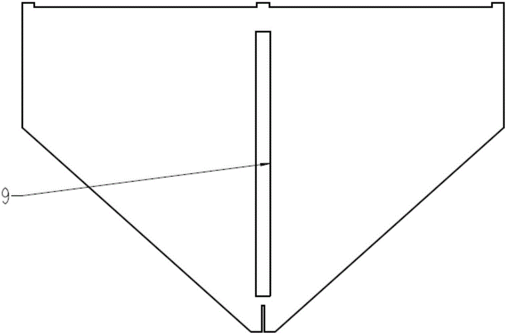
[0021] Further, the radiator 2 is composed of four trapezoidal plates presenting an included angle of 90°. Every two of the four trapezoidal sheets form an overall plane, and there is a crack 9 in the middle of each overall plane, which is used for the two overall planes ...


PUM


Abstract

The invention discloses an ultra-wideband ceiling antenna. The ultra-wideband ceiling antenna is characterized by comprising a loading disc, a radiating body and a base plate, wherein a grounding piece and a supporting column are arranged between the radiating body and the base plate, and a feeder cable penetrates through the base plate and is connected with the radiating body for feeding. The ultra-wideband ceiling antenna almost covers whole UHF frequency bands and part of UWB frequency bands by adopting disc loading, slotting and grounding piece increasing technologies and the like. In addition, a sheet object is adopted as the radiating body, and the ultra-wideband ceiling antenna is simple in structure, low in structure and convenient to produce.

Description

technical field [0001] The invention relates to the technical field of antennas, in particular to an ultra-wideband ceiling antenna. Background technique [0002] With the rapid development of communication technology, the frequency hopping range of modern tactical radio communication in the military is getting wider and wider, the channel capacity in civilian use is constantly expanding, and communication equipment is becoming more and more broadband. These new trends make modern wireless communication systems have increasingly strong requirements for wideband, miniaturization, and low-profile antennas. In daily life, omnidirectional antennas have also been widely used in mobile communications, radio frequency identification, channel detection and other occasions; in military affairs, omnidirectional antennas are also widely used in satellite communications, radar sensor networks, space vehicles and other fields. Compared with mechanical scanning antennas and phased array ...

Claims


Application Information

Patent Timeline
Patent Type & Authority Applications(China)
IPC IPC(8): H01Q1/36H01Q1/48H01Q1/50
CPCH01Q1/36H01Q1/48H01Q1/50Y02D30/70
Inventor 胡世奇隋诚萧霖钟勇吴维检程伟和胡强
Owner 佛山市盛夫通信设备有限公司
Why Eureka
Try Eureka