
Dual-band wide beam width millimeter wave microstrip antenna based on planar monopole antenna

A monopole antenna and microstrip antenna technology, which is applied in the directions of devices, antennas, and antenna grounding devices that make the antennas work in different frequency bands at the same time, and can solve the problems of narrow half-power lobe width, unable to cover areas, and low gain. , to increase the half-power lobe width, improve the communication efficiency, and improve the anti-interference effect.

Inactive Publication Date: 2017-05-31
NO 20 RES INST OF CHINA ELECTRONICS TECH GRP
View PDF3 Cites 15 Cited by
  • Summary
  • Abstract
  • Description
  • Claims
  • Application Information

AI Technical Summary

Problems solved by technology

Each antenna with a combination of structural form and frequency band characteristics has its application scope and occasions. First of all, the current frequency resources are tight and the high-frequency communication frequency band is single, which affects the communication efficiency of the entire radar communication system. What follows is The delay in information acquisition time on the modern battlefield will inevitably delay fighters, so ordinary single-frequency antennas cannot meet the needs; secondly, in the radar communication system, in order to enable the radar to cover a larger control area with its own structure size fixed , the half-power lobe width of the traditional antenna is too narrow to cover a wide range, and when the radar is scanning, it cannot cover a wider area; finally, although the monopole antenna can cover almost omnidirectional in one direction, But the gain is too low, there is no way to meet the application requirements of higher power output and high directivity of the radar system

Method used


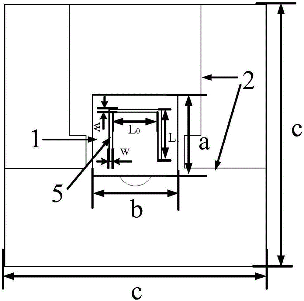
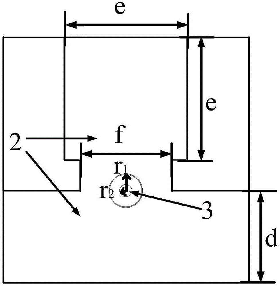
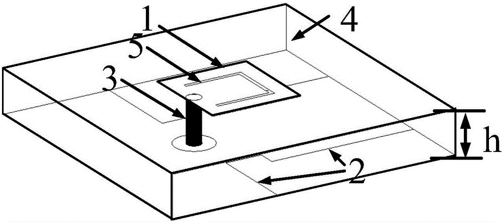
Image

  • Dual-band wide beam width millimeter wave microstrip antenna based on planar monopole antenna
  • Dual-band wide beam width millimeter wave microstrip antenna based on planar monopole antenna
  • Dual-band wide beam width millimeter wave microstrip antenna based on planar monopole antenna

Examples


Embodiment Construction

[0015] The present invention will be further described below in conjunction with the accompanying drawings and embodiments, and the present invention includes but not limited to the following embodiments.

[0016] A wide-beam millimeter-wave microstrip antenna based on a monopole antenna, including a dielectric substrate, a radiation patch, a reflective floor, and a coaxial feeder.

[0017] A U-shaped slot is opened on the radiation patch to form antenna dual-frequency radiation; the reflective floor adopts a patch in the form of a monopole antenna. On the basis of the traditional microstrip patch antenna, the radiation patch, dielectric substrate and The coaxial feeder remains unchanged, the size of the radiation patch is used to control the radiation frequency of the antenna, and the form of the monopole patch as a floor greatly increases the half-power lobe width of the original antenna compared with the traditional full-coverage reflective floor.

[0018] The U-shaped groo...


PUM


Abstract

The invention provides a dual-band wide beam width millimeter wave microstrip antenna based on a planar monopole antenna. The dual-band wide beam width millimeter wave microstrip antenna comprises a dielectric substrate, a radiation patch, a reflecting floor and a coaxial feeder, the radiation patch and the reflecting floor are respectively arranged on both surfaces of the dielectric substrate, a U-shaped groove is formed in a front face of the radiation patch, the reflecting floor adopts a planar patch in the form of the monopole antenna, and the coaxial feeder penetrates through the dielectric substrate to connect the radiation patch and the reflecting floor. The dual-band wide beam width millimeter wave microstrip antenna provided by the invention effectively improves the communication efficiency of a radar system, reduces the effective radiation area of the antenna, greatly improves the semi-power beam width on a specified direction, effectively improves the anti-interference ability of the antenna in a combat communication system, is small in structure and is convenient to combine with a complete machine.

Description

technical field [0001] The invention relates to a microstrip antenna in the millimeter wave band, which is a miniaturized planar monopole antenna structure, which realizes a half-power lobe width of 104° in the horizontal direction and a half-power lobe width of 40° in the vertical direction. Background technique [0002] As the directional receiving and transmitting device of the radar system, the antenna has a variety of structural forms, such as microstrip form, horn form, reflective surface form, spiral shape, symmetrical array, etc.; according to the frequency band characteristics of the antenna, it can be divided into single-band antenna, Dual-band antennas and multi-band antennas. Each antenna with a combination of structural form and frequency band characteristics has its application scope and occasions. First of all, the current frequency resources are tight and the high-frequency communication frequency band is single, which affects the communication efficiency of ...

Claims


Application Information

Patent Timeline
Patent Type & Authority Applications(China)
IPC IPC(8): H01Q1/38H01Q1/48H01Q19/10H01Q5/10H01Q5/307
CPCH01Q1/38H01Q1/48H01Q5/10H01Q5/307H01Q19/104
Inventor 张振龙祁华王传阳
Owner NO 20 RES INST OF CHINA ELECTRONICS TECH GRP
Learn More