Collecting sliding ring grinding device built in electric device and electric device

A technology for electrical equipment and current collection, which is applied in the directions of electrical components, current collector maintenance, circuit/collector components, etc.

Active Publication Date: 2017-05-31
SHOUGANG JINGTANG IRON & STEEL CO LTD
View PDF6 Cites 4 Cited by
  • Summary
  • Abstract
  • Description
  • Claims
  • Application Information

AI Technical Summary

Problems solved by technology

[0005] Aiming at the problems existing in the prior art, the embodiment of the present invention provides a collector slip ring grinding device built in the electrical equipment and the electrical equipment, which are used to solve the problems in the prior art when the surface of the collector slip ring sparks When the phenomenon occurs, it is necessary to shut down the electrical equipment to repair the collector slip ring, which leads to the technical problem that the working efficiency of the electrical equipment is reduced

Method used


Image

  • Collecting sliding ring grinding device built in electric device and electric device
  • Collecting sliding ring grinding device built in electric device and electric device

Examples


Embodiment 1

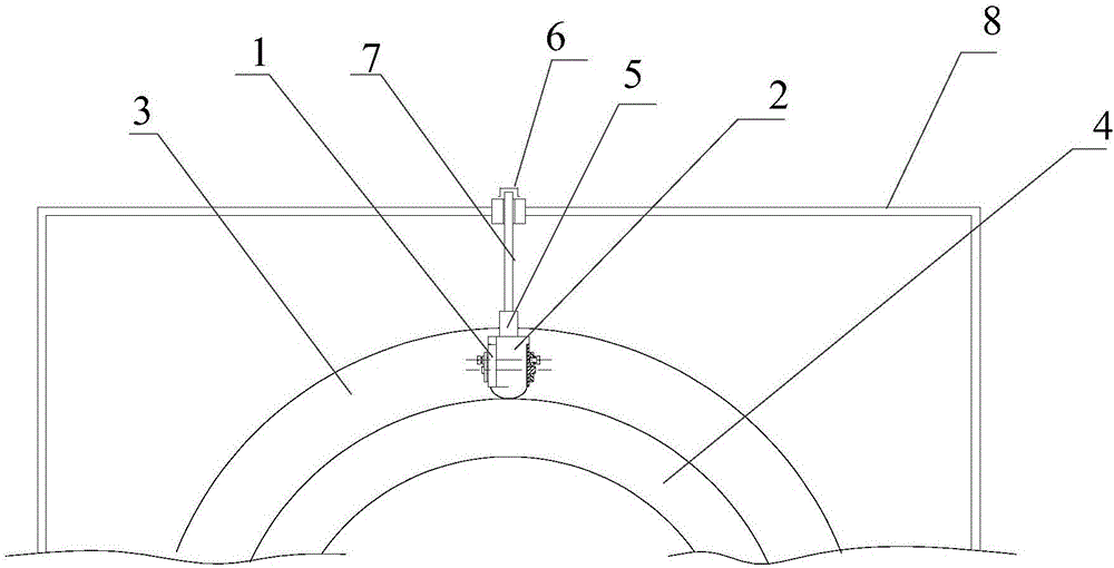
[0028] This embodiment provides a grinding device for the collector slip ring 4, the grinding device is built into the rotating electrical equipment, such as figure 1 As shown, the device includes: a clamping part 1, a grinding tool 2, and a pressing mechanism; wherein,

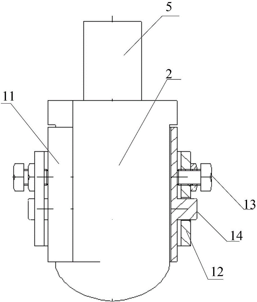
[0029] see figure 2 , the clamping part 1 is fixed on the fixed part 3 on the radially outer side of the collector slip ring 4 by bolts; the fixing part 3 may specifically include a conductive part, and the conductive part may include a current leading busbar, The current introducing bus bar is arranged outside the outer diameter of the collector slip ring 4 . Wherein, because the grinding device composed of the grinding tool 2 and the clamping part 1 is respectively connected to two equipotential conductive parts, there is no need for electrical insulation between the grinding tool 2 and the current introducing bus bar.

[0030] The clamping part 1 includes: an angle adjustment mechanism, and the angle ad...

Embodiment 2

[0043]Corresponding to Embodiment 1, this embodiment also provides an electrical equipment, the electrical equipment includes: a grinding device for the collector slip ring 4, and the grinding device is installed in the chamber of the collector slip ring 4 of the electrical equipment , specifically, as figure 1 As shown, the device includes: a clamping part 1, a grinding tool 2, and a pressing mechanism; wherein,

[0044] The clamping part 1 is fixed on the fixed part 3 on the radially outer side of the collector slip ring 4 by bolts; the fixed part 3 may specifically include a conductive part, and the conductive part may include a current leading busbar, so The current introduction busbar is arranged outside the outer diameter of the collector slip ring 4 . Wherein, because the grinding device composed of the grinding tool 2 and the clamping part 1 is respectively connected to two equipotential conductive parts, therefore, there is no need for electrical insulation between t...

Embodiment 3

[0058] Corresponding to Embodiment 2, when the rotating electrical equipment is the rotor excitation system of a large synchronous motor, the grinding device provided in Embodiment 1 can be used to grind the surface of the collector slip ring 4, as follows:

[0059] Such as figure 1 As shown, the device includes: a clamping part 1, a grinding tool 2, and a pressing mechanism; wherein,

[0060] The clamping part 1 is fixed on the fixed part 3 on the radially outer side of the collector slip ring 4 by bolts; the fixed part 3 may specifically include a conductive part, and the conductive part may include a current leading busbar, so The current introduction busbar is arranged outside the outer diameter of the collector slip ring 4 . Wherein, because the grinding device composed of the grinding tool 2 and the clamping part 1 is respectively connected to two equipotential conductive parts, there is no need for electrical insulation between the grinding tool 2 and the current intro...


PUM


Abstract

The invention provides a collecting sliding ring grinding device built in an electric device and the electric device. The grinding device comprises a clamping part, a grinding tool and a press-down mechanism, wherein the clamping part is fixed to a fixed part on the radial outer side of a collecting sliding ring, the grinding tool is fixed to the interior of the clamping part, one end of the grinding tool is opposite to the surface of the collecting sliding ring, and the press-down mechanism is connected with the other end of the grinding tool and used for making the grinding tool press a to-be-ground surface of the collecting sliding ring so that the grinding tool can make contact with the to-be-ground surface of the collecting sliding ring. The number of the grinding device is at least one, the grinding device is arranged on a current input and gathering copper bar, when the surface of the collecting sliding ring needs to be ground, the press-down mechanism presses the grinding tool to the surface of the collecting sliding ring, the electric device works and drives the collecting sliding ring to rotate, accordingly when the electric device normally works, the surface of the collecting sliding ring can be ground, the electric device is prevented from being stopped, and the work efficiency of the electric device is improved.

Description

technical field [0001] The invention belongs to the technical field of electrical equipment, and in particular relates to a current collector slip ring grinding device built in the electrical equipment and the electrical equipment. Background technique [0002] Rotating electrical equipment mostly adopts the rotating contact method of brush-collector slip ring to introduce current into the rotating electrical equipment. However, due to the characteristics of the frictional contact current conduction structure of the brush-collector slip ring and various other reasons, the problem of ignition and oxidation on the surface of the collector slip ring often occurs, and in severe cases, a layer of Rough oxide film, this oxide film further causes poor contact between the brush and the collector slip ring and aggravates the phenomenon of contact sparking, forming a vicious circle. [0003] In the prior art, in order to solve this problem, the equipment is generally shut down, and t...

Claims


Application Information

Patent Timeline
Patent Type & Authority Applications(China)
IPC IPC(8): H01R43/00H01R43/14
CPCH01R43/00H01R43/14
Inventor 刘海云
Owner SHOUGANG JINGTANG IRON & STEEL CO LTD
Why Eureka
Try Eureka