
Driving method and driving circuit of laser, and application of driving circuit in pump laser

A driving circuit and driving method technology, used in lasers, laser parts, semiconductor lasers, etc., can solve problems such as inability to adapt to energy consumption standards, output power changes, and product performance deterioration, and achieve good market competitiveness and high efficiency. The effect of improving the road gain and flexibility

Pending Publication Date: 2017-05-31
LOOTOM TELCOVIDEO NETWORK WUXI
View PDF4 Cites 4 Cited by
  • Summary
  • Abstract
  • Description
  • Claims
  • Application Information

AI Technical Summary

Problems solved by technology

For example, the Chinese invention patent with the notification number CN203338172U discloses a semiconductor laser constant current drive system, which records the use of a linear voltage regulation method that controls the NMOS transistor Q1. This method has low efficiency and large heat generation, resulting in inability to To adapt to the increasingly stringent energy consumption standards and the application of small volume occasions, it also uses the traditional adjustment method to manually adjust the size of the semiconductor laser drive current through the variable resistor, the production efficiency is low, and the variable resistor is aging during use. The current is unstable, and the aging of the laser causes the output power to change, resulting in poor product performance

Method used


Image

  • Driving method and driving circuit of laser, and application of driving circuit in pump laser
  • Driving method and driving circuit of laser, and application of driving circuit in pump laser

Examples


Embodiment Construction

[0014] The technical solutions in the embodiments of the present invention will be clearly and completely described below in conjunction with the drawings in the embodiments of the present invention. Apparently, the described embodiments are only some of the embodiments of the present invention, not all of them. Based on the embodiments of the present invention, all embodiments obtained by those skilled in the art without making creative efforts belong to the protection scope of the present invention.

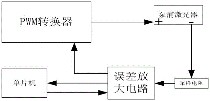
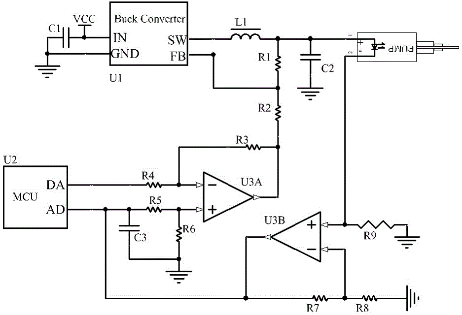
[0015] A laser driving method of the present invention is used to drive a pump laser, and the change of the working current of the pump laser is collected through a sampling resistor, and the change of the collected current signal is converted into a change of a voltage signal, and the voltage signal is amplified by an error amplifier circuit Then send it to the single-chip microcomputer, the single-chip microcomputer outputs the digital control signal to the error amplifier ci...


PUM


Abstract

The invention discloses a driving method of a laser. A single chip microcomputer is adopted to control a PWM converter to realize adjustment of the working current of the laser; the adjustment is simple and convenient, the control efficiency is high, and the flexibility is greatly improved; working current change of the laser is collected by a sampling resistor; the collected current signal changes are converted into voltage signal changes; the voltage signal is amplified by an error amplifying circuit and then transmitted to the single chip microcomputer; the single chip microcomputer outputs a digital control signal to the error amplifying circuit according to the voltage signal input by the error amplifying circuit; the error amplifying circuit adjusts the output voltage and transmits to the PWM converter; and the PWM converter adjusts output duty ratio so as to adjust the working current of the whole laser. Meanwhile, the invention provides a driving circuit of the laser and an application of the driving circuit in a pump laser.

Description

technical field [0001] The invention belongs to the technical field of laser drive, in particular to a laser drive method, a drive circuit and an application in a pump laser. Background technique [0002] In the prior art, the drive circuit of the pump laser is mainly in the linear drive mode. For example, the Chinese invention patent with the notification number CN203338172U discloses a semiconductor laser constant current drive system, which records the use of a linear voltage regulation method that controls the NMOS transistor Q1. This method has low efficiency and large heat generation, resulting in inability to To adapt to the increasingly stringent energy consumption standards and the application of small volume occasions, it also uses the traditional adjustment method to manually adjust the size of the semiconductor laser drive current through the variable resistor, the production efficiency is low, and the variable resistor is aging during use. The current is unstab...

Claims


Application Information

Patent Timeline
IPC IPC(8): H01S5/042
CPCH01S5/042
Inventor 马金满吴光英李刚庄小正柯贤智徐闯吴志峰
Owner LOOTOM TELCOVIDEO NETWORK WUXI
Learn More