Substation operation room dehumidification system

A technology for operating rooms and substations, applied in the field of dehumidification systems in substation operating rooms, can solve problems such as heat exchanger damage, heat exchanger humid air erosion and oxidation, affecting the normal operation of electrical equipment in the machine room, etc., to achieve uniform heating and ensure dehumidification efficiency. , Improve the effect of connection stability

Inactive Publication Date: 2017-05-31
重庆靠岸机电设备有限公司
View PDF0 Cites 0 Cited by
  • Summary
  • Abstract
  • Description
  • Claims
  • Application Information

AI Technical Summary

Problems solved by technology

In the traditional dehumidifier, due to the high content of water vapor in the working environment, the heat exchanger is easily eroded and oxidized by the humid air when exchanging heat with the air, which in turn causes damage to the heat exchanger and affects the normal operation of the electrical equipment in the machine room. Work

Method used


Image

  • Substation operation room dehumidification system
  • Substation operation room dehumidification system
  • Substation operation room dehumidification system

Examples


Embodiment 1

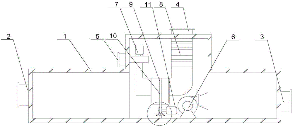
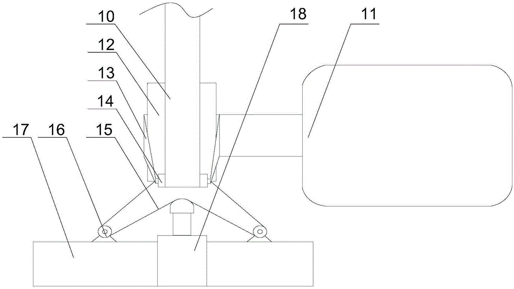
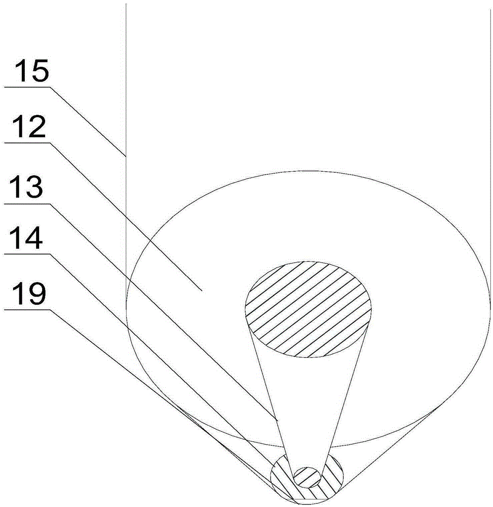
[0024] Such as figure 1 , figure 2 with Figure 5 As shown, a dehumidification system for a substation operation room of the present invention includes a casing 1, on which an air inlet 2, an air outlet 3, a regeneration air inlet 4, and a regeneration air outlet 5 are provided. 1 is installed with a fan 6, a heater 8, a dehumidification rotor 9 and a regeneration fan 7, one end of the fan 6 is connected to the air inlet 2, the other end of the fan 6 is connected to the air outlet 3, and the heater 8 is connected to The regeneration air inlet 4, the dehumidification rotor 9 and the regeneration fan 7 are connected in sequence. The other end of the regeneration fan 7 is connected to the regeneration air outlet 5. The output end of the motor 11 is equipped with a pulley 12, which also includes a pulley 12 The roller 14 is arranged tangentially. The pulley 12, the roller 14 and the dehumidifying wheel 9 are connected by a belt 10, and a pressure sensor 19 is installed at the tang...

Embodiment 2

[0028] Such as image 3 As shown, in this embodiment on the basis of Embodiment 1, the connecting rod 13 is an elastic plastic rod, and both ends of the elastic plastic rod are sleeved on the rotating shafts of the pulley 12 and the roller 14 respectively. In order to prevent the roller 14 from moving with the belt 10 when it rotates, the connecting rod 13 connects the pulley 12 with the roller 14. When the roller 14 is pulled at the output end of the cylinder 18, the connecting rod 13 made of elastic plastic will deform slightly. It adapts to the movement of the roller 14 while ensuring the advantageous support of the roller 14.

Embodiment 3

[0030] Such as Figure 4 As shown, this embodiment is based on the first embodiment. One end of the connecting rod 13 is provided with a through hole, the rotating shaft of the pulley 12 is in clearance fit with the through hole, and the other end of the connecting rod 13 is hinged with the rotating shaft of the roller 14. Preferably, a through hole is opened at one end of the connecting rod 13, and the shaft of the pulley 12 is in clearance fit with the through hole. When the roller 14 is displaced to a certain extent, the connecting rod 13 moves with the roller 14 to ensure favorable support for the roller 14.


PUM


Abstract

The invention discloses a substation operation room dehumidification system. The substation operation room dehumidification system comprises an enclosure; an air inlet, an air outlet, a regeneration air inlet and a regeneration air outlet are arranged on the enclosure; a fan, a heater, a dehumidification rotation wheel and a regeneration fan are installed in the enclosure; a belt wheel is installed on the output end of the motor; an idler wheel, which is tangent to the belt wheel, is also included; a pressure sensor is installed at the tangent position of the idler wheel and a belt; a cylinder and multiple fixed pulleys are installed on a bracket; the multiple fixed pulleys are symmetrically arranged at two sides of the output end of the cylinder; two ends of the rotating shaft of the idler wheel are connected to a pull wire; furthermore, the pull wire bypasses the fixed pulleys and the output end of the cylinder, so that a pulley set is formed; the output end of the cylinder extends forwardly, so that the rotating shaft of the idler wheel is pulled; therefore, the tension of the belt is restored; normal rotation of the dehumidification rotation wheel and the belt wheel is ensured; the connection stability of the dehumidification rotation wheel and the motor is improved while water vapour in a hydropower station operation room can be eliminated conveniently and rapidly; and thus, the dehumidification efficiency of the dehumidification rotation wheel is ensured.

Description

Technical field [0001] The invention relates to a dehumidifier, in particular to a dehumidification system for a substation operation room. Background technique [0002] All kinds of electrical equipment in the electrical machine room have higher environmental requirements, so dehumidification equipment is required in the machine room. The dehumidifier is composed of a compressor, a heat exchanger, a fan, a water container, a cabinet and a controller. Its working principle is: the fan draws moist air into the machine and passes through the heat exchanger. At this time, the moisture in the air condenses It becomes water droplets and turns into dry air to be discharged out of the machine. This circulation reduces indoor humidity. In the traditional dehumidifier, due to the high content of water vapor in the working environment, the heat exchanger is easily eroded and oxidized by the humid air when the air is heat exchanged, which will cause the heat exchanger to be damaged and aff...

Claims


Application Information

Patent Timeline
Patent Type & Authority Applications(China)
IPC IPC(8): H02B1/56
CPCH02B1/565
Inventor 陈启友
Owner 重庆靠岸机电设备有限公司
Why Eureka
Try Eureka