Charging device and charging method

A charging device and charging method technology, applied in circuit devices, battery circuit devices, secondary battery charging/discharging and other directions, can solve the problems of reducing battery charging heat, current inversion, and reducing the layout area of ​​printed circuit boards, etc. Reduce heat generation, reduce layout area, and solve the effect of current backflow

Inactive Publication Date: 2017-05-31
YULONG COMPUTER TELECOMM SCI (SHENZHEN) CO LTD
View PDF3 Cites 1 Cited by
  • Summary
  • Abstract
  • Description
  • Claims
  • Application Information

AI Technical Summary

Problems solved by technology

[0003] In view of the above, it is necessary to provide a charging device and method, which can solve the problem of current backflow during the charging process, which can not only reduce the cost, but also reduce the heat generated when the battery is charged, and reduce the layout area of ​​the printed circuit board.

Method used


Image

  • Charging device and charging method
  • Charging device and charging method
  • Charging device and charging method

Examples


Embodiment Construction

[0032] In order to make the object, technical solution and advantages of the present invention clearer, the present invention will be described in detail below in conjunction with the accompanying drawings and specific embodiments.

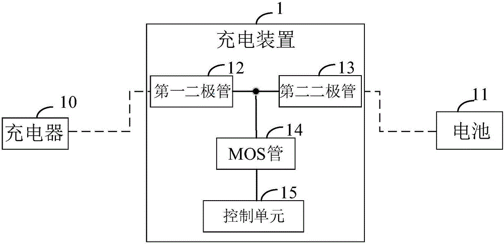
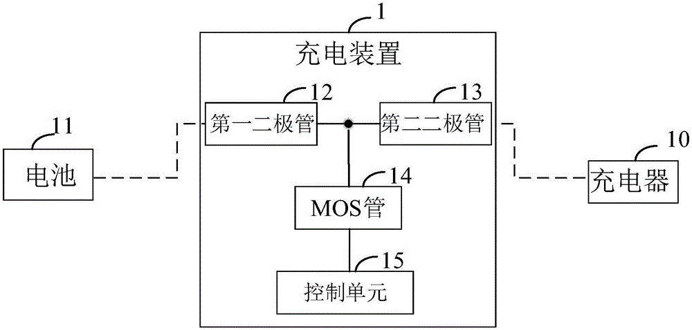
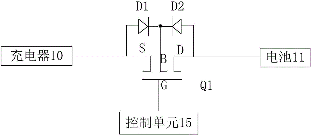
[0033] Such as figure 1 as shown, figure 1 It is a schematic diagram of the charging device of the first preferred embodiment of the present invention. The charging device 1 can be connected with the charger 10 and the battery 11, the charging device 1 includes two diodes, a MOS transistor 14 and a control unit 15, and the two diodes include a first diode D1 and a second diode The transistor D2, the MOS transistor 14 includes a substrate B, a gate G, a source S and a drain D.

[0034] In at least one embodiment of the present invention, the anode of the first diode D1 is connected to the source S of the MOS transistor 14, and the anode of the second diode D2 is connected to the drain of the MOS transistor 14. The pole D is connected; there is a...


PUM


Abstract

The invention provides a charging device. The charging device can be connected with a charger and a battery and comprises a first diode, a second diode, an MOS transistor and a control unit, wherein the MOS transistor comprises a substrate, a gate, a source and a drain; a node is arranged between a cathode of the first diode and the cathode of the second diode and connected with a substrate of the MOS transistor; the control unit is connected with the gate; and the control unit detects a charging state of the battery, controls on/off of the MOS transistor according to the charging state and controls charging of the battery. The invention further provides a charging method. By using the charging method and the charging device, the problem of current backflow in the charging process can be solved; the cost can be reduced; heat emission when the battery is charged can be reduced; and the layout area of a printed circuit board is reduced.

Description

technical field [0001] The invention relates to the technical field of charging, in particular to a charging device and a charging method. Background technique [0002] The charging circuit for low-voltage charging in the prior art directly controls the charging of the battery through two MOS (Metal Oxide Semiconductor, metal oxide semiconductor) tubes. Although this charging circuit can improve charging efficiency, it is difficult to control the charging process. Although the charging circuit can solve the problem of current backflow when an accident occurs during charging, the use of two MOS tubes increases the cost, and the impedance of the charging circuit will also increase, causing the battery to heat up. Contents of the invention [0003] In view of the above, it is necessary to provide a charging device and method, which can solve the problem of current backflow during the charging process, which can not only reduce the cost, but also reduce the heating of the bat...

Claims


Application Information

Patent Timeline
Patent Type & Authority Applications(China)
IPC IPC(8): H02J7/00H01M10/44
CPCH01M10/44H02J7/0036H02J7/0048H02J7/00309Y02E60/10
Inventor 涂瑞高思
Owner YULONG COMPUTER TELECOMM SCI (SHENZHEN) CO LTD
Why Eureka
Try Eureka