Ultra-thin side circuit conductive ring

A conductive ring and circuit technology, applied in the direction of electrical components, electromechanical devices, electric components, etc., can solve the problem that the thickness of the conductive ring cannot be reached, and achieve the effect of ensuring durability

Pending Publication Date: 2017-05-31
吴江天龙电子机械设备有限公司
View PDF4 Cites 8 Cited by
  • Summary
  • Abstract
  • Description
  • Claims
  • Application Information

AI Technical Summary

Problems solved by technology

[0004] In the prior art, conductive fibers are generally evenly bonded to the inner circumference of the shell of the conductive ring through conductive glue. If the conductive fibers want to

Method used


Image

  • Ultra-thin side circuit conductive ring
  • Ultra-thin side circuit conductive ring
  • Ultra-thin side circuit conductive ring

Examples


Example Embodiment

[0026] Example 1

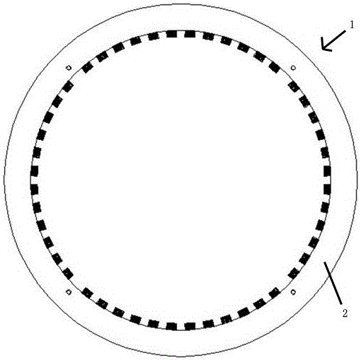
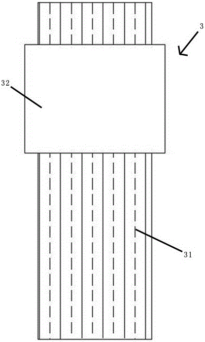
[0027] The annular outer cover (2) includes a front outer cover (21) and a rear outer cover (22). A fixing member is provided on the inner circumference of the front outer cover (21) or the rear outer cover (22). The part is a fixing groove (24). After the copper sleeve (32) is placed in the fixing groove (24), the front outer cover (21) and the rear outer cover (22) are closed and locked, and the conductive fiber bundle (31) is It is fixed on the ring-shaped outer cover (2) through a conductive sleeve.

Example Embodiment

[0028] Example 2

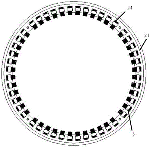
[0029] Such as figure 2 and Figure 5 As shown, the annular outer cover (2) includes a front outer cover (21), a fixing ring (23) and a rear outer cover (22), such as Figure 4 The fixing ring (23) shown is evenly distributed with fixing parts, which are fixing grooves (24). After the copper sleeve (32) is placed in the fixing groove (24), the fixing ring is placed on the front outer cover ( 21) In the middle of the rear outer cover (22), the soft rear locks the front outer cover and the rear outer cover, and the conductive fiber bundle (31) is fixed on the annular outer cover through the conductive sleeve.


PUM

PropertyMeasurementUnit
Thicknessaaaaaaaaaa

Abstract

The invention discloses an ultra-thin side circuit conductive ring. The ultra-thin side circuit conductive ring comprises an annular outer cover and conductive elements arranged on the annular outer cover; the conductive elements comprise at least one conductive fiber bundle and a conductive sleeve for fixing the conductive fiber bundles; a fixing part used for fixing the conductive sleeve is arranged on the annular outer cover; and the conductive fiber bundles and a motor shaft are in interference contact. By adopting a novel structure, the problem existing in realization of stability and fastening of the conductive fiber bundles on the annular outer cover under relatively thin thickness requirement is solved; and fixation and durability of conductivity are fully guaranteed.

Description

technical field [0001] The invention relates to the field of motors, in particular to a conductive ring of a motor. Background technique [0002] When the frequency conversion of the new energy vehicle motor is performed, the voltage on the shaft will increase, and the shaft voltage will be released through the bearing through the current. When the current is released, the surface of the bearing race and the ball is galvanically corroded, and the corrosion process is slow. In this process, the driver will feel that the power of the new energy vehicle is getting smaller and smaller. When the car is lying down, the bearing of the car motor has been damaged, which is manifested by blackening of grease, melting pits on the surface of the bearing race and balls, and the particles in the melting pit layer are sealed in the bearing by the sealed bearing. These reasons eventually lead to the failure of the bearing Shorter lifespan. [0003] Therefore, in order to prevent the occu...

Claims


Application Information

Patent Timeline
IPC IPC(8): H02K11/00
CPCH02K11/0094Y02T10/64
Inventor 王俊华刘文辉钱嘉诚江海
Owner 吴江天龙电子机械设备有限公司
Why Eureka
Try Eureka