
Control methods of discrete PWM and multi-channel PWM and LED system

An LED system and control method technology, applied in the field of LED systems, can solve the problems of eye fatigue, inability to generate high-frequency PWM waveforms, obvious flicker, etc., and achieve the effects of reducing energy consumption, simplifying power drive circuits, and uniform light distribution

Active Publication Date: 2017-05-31
XIAMEN UNIV OF TECH
View PDF2 Cites 4 Cited by
  • Summary
  • Abstract
  • Description
  • Claims
  • Application Information

AI Technical Summary

Problems solved by technology

[0006] 3) In LED control, if the frequency is too low, the flicker will be more obvious, which will easily cause eye fatigue
For some low-end single-chip microcomputers, because the system frequency and number of digits are determined, it may not be possible to generate high-frequency PWM waveforms at all.

Method used


Image

  • Control methods of discrete PWM and multi-channel PWM and LED system
  • Control methods of discrete PWM and multi-channel PWM and LED system
  • Control methods of discrete PWM and multi-channel PWM and LED system

Examples


Embodiment Construction

[0033] The present invention will be further described below in conjunction with the accompanying drawings and specific embodiments.

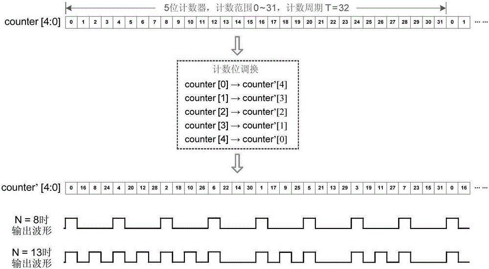
[0034] A discrete PWM control method: exchange the high and low positions of each count bit of the counter count value M to obtain a new count value M';

[0035] When outputting a pulse waveform with a duty ratio of N / T, where T is the counting cycle of the counter; when M'

[0036] The exchanging the high and low positions of each count bit of the count value M of the counter specifically refers to: swap the lowest bit and the highest bit of the count value M, exchange the second highest bit with the second lowest bit, and so on. It should be pointed out that the replacement method is not limited to the above-mentioned one, it is only an optimized method, and should not limit the protection scope of the present invention. For example, the discreti...


PUM


Abstract

The invention provides a control method of a discrete PWM. The height position of each count digit of a counter counting value M is changed to obtain a new counting value M'; a pulse waveform with the duty ratio of N / T is outputted; when M' is smaller than N, the outputted pulse waveform is a high level; and when the M' is larger than or equal to N, the outputted pulse waveform is a low level. The invention also provides a control method of a multi-channel discrete PWM, the height position of each count digit of the counter counting value M is changed to obtain a new counting value M'; the counting period T of a counter is divided into at least two intervals, and each interval is corresponding to one channel; when the counting value M' is in a first interval, the first channel outputs a high level, and when the counting value M' is outside the first interval, the first channel outputs a low level; when the counting value M' is in a second interval, the second channel outputs a high level, and when counting value M' is outside the second interval, the second channel outputs a low level, and so on.

Description

technical field [0001] The invention relates to a control method of pulse width modulation and an LED system applying the method. Background technique [0002] PWM is pulse width modulation, which is a pulse waveform with a variable duty cycle. It is a very effective technology for controlling analog circuits by using the digital output of a microprocessor. It is widely used in many fields from measurement and communication to power control and conversion. [0003] For example, in LED control, it is necessary to adjust the brightness of LED light. If the brightness is adjusted by the current, it is too complicated. In order to save costs, PWM technology will be used in the industry to adjust the brightness of the screen. PWM achieves the purpose of modulation by adjusting the duty cycle. The frequency of the waveform itself does not participate in the adjustment of the duty cycle, but the frequency will have some important effects, such as: [0004] 1) In motor control,...

Claims


Application Information

Patent Timeline
IPC IPC(8): H05B33/08H05B44/00
CPCH05B45/00Y02B20/30
Inventor 何一凡朱顺痣
Owner XIAMEN UNIV OF TECH
Learn More