Heat pump heating apparatus

A heating device and heat pump technology, applied in the field of heat pump heating devices, can solve the problems of insufficient heating capacity of the heating terminal, and achieve the purpose of avoiding the temperature drop of the heated space, avoiding the feeling of insufficient heating, suppressing the suction temperature and Effect of Abnormal Increase in Suction Pressure

Inactive Publication Date: 2017-05-31
SANDEN CORP
View PDF7 Cites 4 Cited by
  • Summary
  • Abstract
  • Description
  • Claims
  • Application Information

AI Technical Summary

Problems solved by technology

[0005] In this way, the conventional heat pump heating device judges that the heating capacity of the heating terminal is insufficient based on the return temperature of the

Method used


Image

  • Heat pump heating apparatus
  • Heat pump heating apparatus
  • Heat pump heating apparatus

Examples


Embodiment

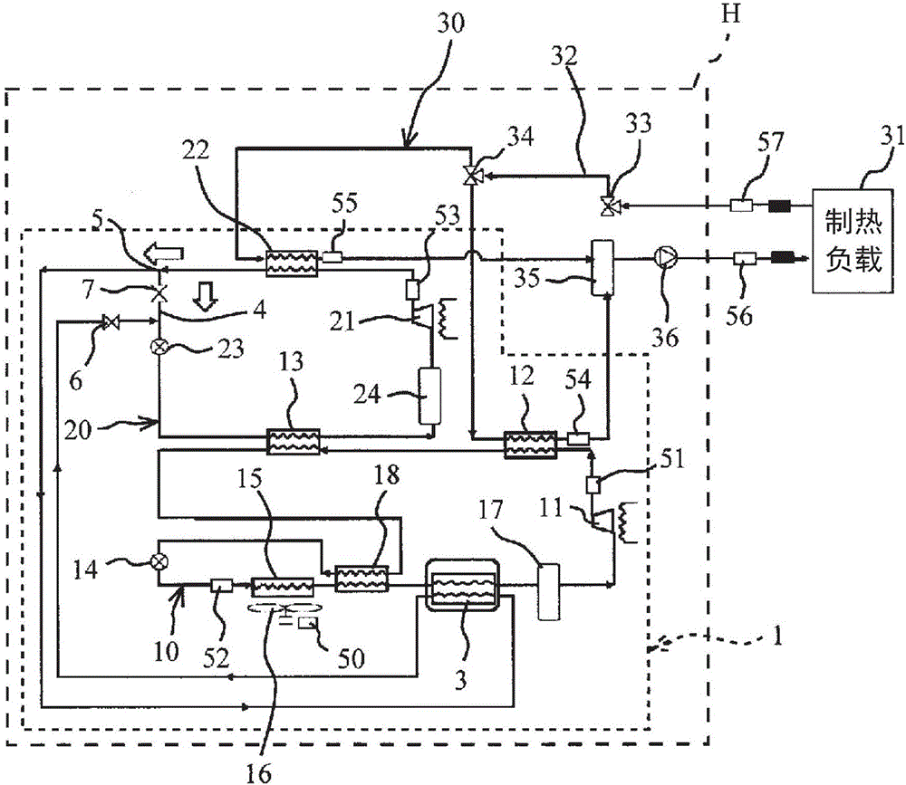
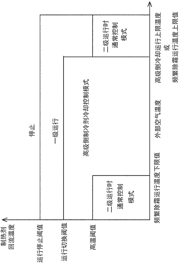
[0089] Next, an example using the heat pump heating device according to the present invention will be described. In this example, the heat pump type heating device H according to the above-mentioned present embodiment was used. In this embodiment, the operating conditions are set as follows: the outflow temperature of the refrigerant is 70°C, the external air temperature is -10°C, the operating frequency of the compressor 11 on the low-pressure side is 80 Hz, and the operating frequency of the compressor 21 on the high-pressure side is 51 Hz. The heat medium circulation flow rate is 5.6L / min in the normal control mode during the secondary operation, and 4.4L / min in the high-level side refrigerant cooling control mode (when the heat medium return temperature is 58°C). Referring to the drawings, the following discusses the case of changing the refrigerant return temperature while maintaining the normal control mode during the secondary operation, and the case of changing the ref...


PUM


Abstract

The purpose of the present invention is to provide a heat pump heating apparatus that is able to continue two-stage operation without having to stop a high-stage compressor when the return temperature of a heat carrier reaches a prescribed high temperature and is hence able to mitigate the feeling of insufficient heating caused by the high-stage side compressor being stopped as well as the feeling of insufficient heating caused by frequent defrosting operations. To achieve this objective, this heating apparatus is provided with: an internal heat exchanger (second internal heat exchanger) in which a low-temperature refrigerant on the low-pressure side of a low-stage side refrigeration circuit and a high-temperature refrigerant on the high-pressure side of a high-stage side refrigeration circuit exchange heat; a bypass pipe for bypassing the internal heat exchanger; and a flow channel-regulating means for regulating the refrigerant circulation in the internal heat exchanger and in the bypass pipe.

Description

technical field [0001] The present invention relates particularly to a heat pump type heating device using a two-stage compression type heat pump unit. Background technique [0002] Conventionally, this type of heat pump heating apparatus uses a refrigeration circuit that circulates a refrigerant as a heat pump unit to generate hot water for heating and the like. For example, the heat pump type heating device disclosed in Patent Document 1 includes: a heating unit that circulates a heating agent through a heating terminal; a primary side heat pump unit that sequentially circulates a refrigerant through circulating through the first compressor, the first heat exchanger, the cascade heat exchanger, the first expansion valve, and the evaporator, and exchanging heat with the heating medium of the heating unit in the first heat exchanger; and two a stage-side heat pump unit, the secondary-side heat pump unit circulates the refrigerant sequentially through the second compressor, ...

Claims


Application Information

Patent Timeline
IPC IPC(8): F25B7/00F24F11/02F25B1/00F25B41/04
CPCF25B5/04F25B6/04F25B9/008F25B25/005F25B40/00F25B49/02F25B2309/061F25B2339/047F25B2700/2106F25B2700/21152F25B2700/21161F25B2700/21174F25B7/00F24F11/89
Inventor 高山靖则石田广酒井祐人根岸洋一
Owner SANDEN CORP
Why Eureka
Try Eureka