
Plate punching device

A punching device and board technology, applied in wood processing equipment, fixed drilling machines, bark area/debris/dust/waste removal, etc., can solve the problem of increased manual workload, inaccurate positioning, relative position error, etc. Problems, low maintenance cost, stable clamping and punching, and regular waste collection and treatment

Active Publication Date: 2017-06-09
浙江金丰人防设备有限公司
View PDF8 Cites 16 Cited by
  • Summary
  • Abstract
  • Description
  • Claims
  • Application Information

AI Technical Summary

Problems solved by technology

However, using the scale line for positioning is easy to cause inaccurate positioning due to inaccurate fixation or other unavoidable problems, and when a plate needs to be punched with multiple holes, it needs to be disassembled and repositioned multiple times, which can easily cause relative position errors. At the same time, wood chips and other residues were not processed and collected in time, which increased the amount of manual work

Method used


Image

  • Plate punching device
  • Plate punching device
  • Plate punching device

Examples


Embodiment Construction

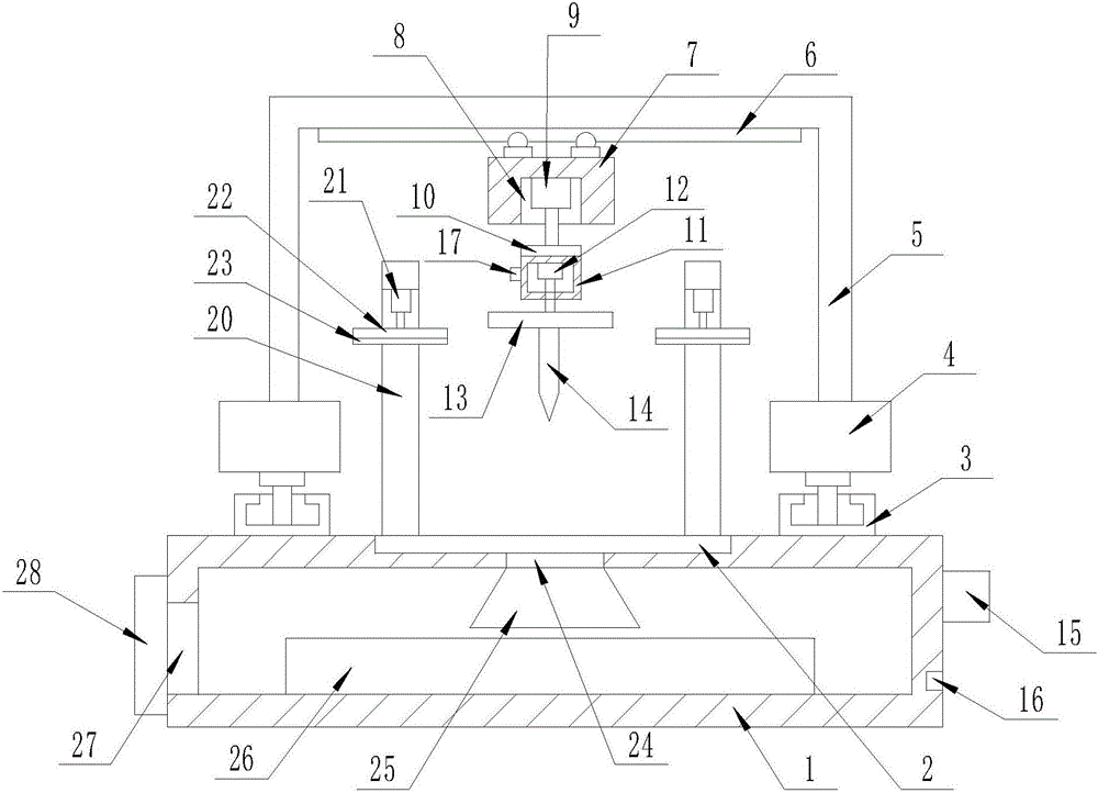
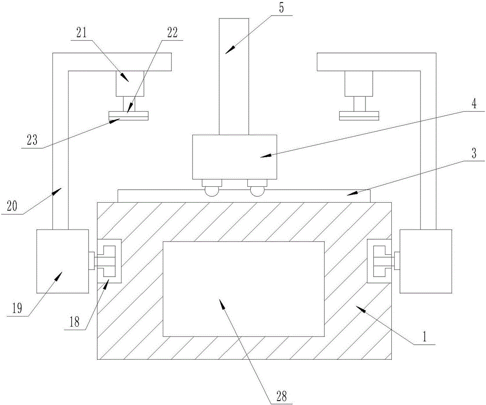
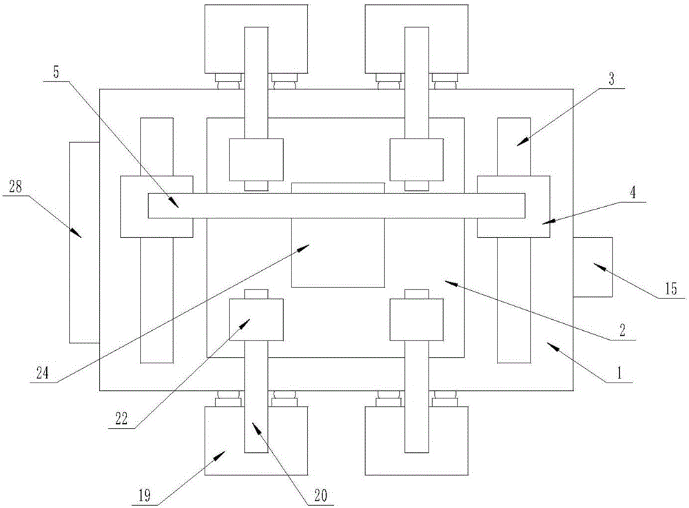
[0016] The present invention is specifically described below in conjunction with accompanying drawing, as Figure 1-3 As shown, a plate punching device includes a workbench (1), the interior of the workbench (1) is a cavity structure, and the center of the upper surface of the workbench (1) is processed with a rectangular groove (2), No. 1 slide rails (3) are provided on both sides of the upper surface of the workbench (1), and No. 1 electric trolleys (4) are provided on each of the No. 1 slide rails (3). The upper surface of the trolley (4) is jointly connected with a gantry (5), the lower surface of the beam of the gantry (5) is provided with a No. 2 slide rail (6), and the No. 2 slide rail (6) is provided with two No. 2 electric trolley (7), the lower surface of the No. 2 electric trolley (7) is processed with a circular groove (8), and the linear motor (9) with the telescopic end downward is arranged in the circular groove (8) , the telescopic end of the linear motor (9) ...


PUM


Abstract

The invention discloses a plate punching device. The plate punching device comprises a workbench, wherein the inner part of the workbench is in a cavity structure; a rectangular groove is formed in the center of the upper surface of the workbench; No.1 sliding rails are respectively arranged on two sides of the upper surface of the workbench; No.1 electric trolleys are respectively arranged on the No.1 sliding rails; the upper surfaces of the No.1 electric trolleys are together connected with a door-shaped frame; a No.2 sliding rail is arranged on the lower surface of a transverse beam of the door-shaped frame; a No.2 electric trolley is arranged on the No.2 sliding rail; a controller is arranged on the surface of one side of the workbench; a city power supply interface is arranged below the controller, and is electrically connected with the controller; and the input end of the controller is electrically connected with the No.1 electric trolleys, the No.2 electric trolley, a linear motor and a rotating motor separately. The plate punching device disclosed by the invention has the beneficial effects that operation is simple; clamping operation and punching operation are stable; position deviation can be avoided; waste can be regularly collected and disposed of; the working environment is neat; usage is convenient; and novelty is high.

Description

technical field [0001] The invention relates to the field of sheet material punching, in particular to a sheet material punching device. Background technique [0002] Driven by new technology, the traditional plate processing technology has been unable to meet the current social needs. In the prior art, for example, CN203875979U discloses a plate punching device, which uses a scale arranged on the same straight line to adjust the position of the punching, and uses a brush to block wood chips and prevent dust from splashing around. However, using the scale line for positioning is easy to cause inaccurate positioning due to inaccurate fixation or other unavoidable problems, and when a plate needs to be punched with multiple holes, it needs to be disassembled and repositioned multiple times, which can easily cause relative position errors. At the same time, residues such as sawdust were not processed and collected in time, which increased the amount of manual work. Contents ...

Claims


Application Information

Patent Timeline
IPC IPC(8): B27C3/02B27G3/00
CPCB27C3/02B27G3/00
Inventor 封红雨
Owner 浙江金丰人防设备有限公司
Learn More