A kind of cast-in-place stair formwork reinforcement structure

A formwork reinforcement and stair technology, which is applied in the direction of formwork/formwork/work frame, building structure, and on-site preparation of building components, which can solve the problem of difficulty in meeting vertical flatness requirements, insufficient leveling operation space, and stability To solve problems such as poor performance, achieve the effect of improving tread leveling operation, improving formwork support method, and strengthening stability

Inactive Publication Date: 2017-06-09
HUBEI JINGBIAO CONSTR ENG CO LTD
View PDF0 Cites 2 Cited by
  • Summary
  • Abstract
  • Description
  • Claims
  • Application Information

AI Technical Summary

Problems solved by technology

[0002] The traditional method of strengthening the cast-in-place stair formwork is generally to use tools such as wooden braces and iron wires to reinforce the kick plate. It is inconvenient to support the formwork on site, making it difficult to meet the requirements for verticality and flatness.
At the same time, due to the poor stress, poor stability, and poor integrity of the single structure of the horizontal and vertical support points, the traditional formwork support method for stairs has large deformation during construction.
Moreover, in the process of leveling the steps, the support bars and iron wires used to reinforce the formwork are in contact with the surface of the concrete steps, and the leveling trowel cannot be extended into the leveling, which is inconvenient
[0003] Through the above-mentioned analysis and induction of the traditional method of stair formwork reinforcement, it is concluded that improper reinforcement methods, poor stability of the formwork, and insufficient space for flattening the formwork are the main factors affecting the appearance of the staircase.

Method used


Image

  • A kind of cast-in-place stair formwork reinforcement structure
  • A kind of cast-in-place stair formwork reinforcement structure

Examples


Embodiment Construction

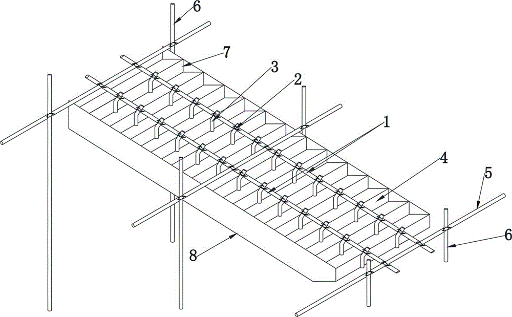
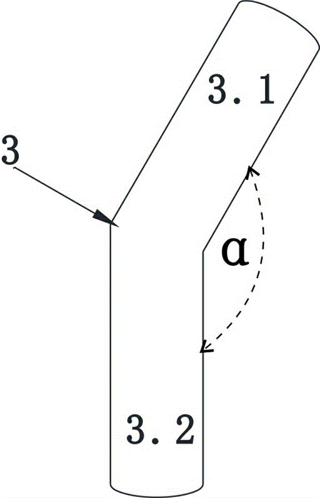
[0018] Such as figure 1 . As shown in 2, a cast-in-place stair formwork reinforcement structure includes longitudinal fixing rods 1 arranged obliquely along the step surface of the building body. There are at least two longitudinal fixing rods 1, preferably two in this embodiment, two Longitudinal fixed rods 1 are arranged on both sides of the stair surface. Fastener 2 is preferably a cross fastener common to construction site leaders.

[0019] Each longitudinal fixing rod 1 is fixed with a plurality of reinforcements 3 through cross fasteners 2 at equal intervals from top to bottom, and the reinforcements 3 are against the formwork 4 of the kick surface. Because it is two longitudinal fixed rods 1, the kick surface template 4 on the same stepping surface is pressed against by two reinforcements 3 . The two longitudinal fixing rods are arranged horizontally to each other and are located on the step surface of the building body in an inclined shape. In this way, the two rein...


PUM


Abstract

A cast-in-place stair formwork reinforcement structure, comprising longitudinal fixing rods arranged obliquely along the step surface of the building, at least two of the longitudinal fixing rods, and each longitudinal fixing rod passes through buckles at equal intervals from top to bottom A plurality of reinforcements are fixed on the piece, and the reinforcements are against the step formwork, and the step formwork on the same step surface is supported by at least two reinforcements. The present invention is a cast-in-place stair formwork reinforcement structure, which improves the drawbacks of the traditional cast-in-place stair formwork arrangement, and uses a new cast-in-place stair formwork reinforcement, which has a very simple structure, convenient construction and operation, labor and time saving, good molding appearance and low cost. Low cost, can be used repeatedly, saving engineering cost and so on.

Description

technical field [0001] The invention relates to the field of building construction reinforcement, in particular to a cast-in-place stair formwork reinforcement structure. Background technique [0002] The traditional method of strengthening the cast-in-place stair formwork is to use wooden braces, iron wires and other tools to reinforce the kick plate. It is inconvenient to set up the formwork on site, making it difficult to meet the requirements for verticality and flatness. At the same time, due to the poor stress, poor stability, and poor integrity of the single structure of the horizontal and vertical support points, the traditional formwork support method for stairs has large deformation during construction. And in the process of leveling the steps, the support bars and iron wires used to reinforce the formwork contact with the surface of the concrete steps, so the leveling trowel cannot stretch into the leveling and is inconvenient. [0003] Through the above-mentione...

Claims


Application Information

Patent Timeline
IPC IPC(8): E04G13/06
Inventor 毛家平余卫王振宇伍学兵程成
Owner HUBEI JINGBIAO CONSTR ENG CO LTD
Why Eureka
Try Eureka