Placement mechanism of high-precision equipment working condition monitoring system

A monitoring system, high-precision technology, applied in the direction of mechanical equipment, supporting machines, machines/supports, etc., can solve the problems that affect the quality of information collection or monitoring, increase the total cost of precision instrument monitoring, consume a lot of time and physical strength, etc. , to achieve the effect of improving service life, effective data support, and reducing mutual wear

Inactive Publication Date: 2017-06-09
重庆靖画工具有限公司
View PDF0 Cites 0 Cited by
  • Summary
  • Abstract
  • Description
  • Claims
  • Application Information

AI Technical Summary

Problems solved by technology

The most common installation method for monitoring equipment is usually to install a pole-type surveillance camera near the instrument. This installation method uses duckbill brackets and iron wires to fix the camera. However, during long-term use, the iron wire or duckbill bracket Corrosion will occur and the camera will become loose, which will affect the quality of information collection or monitoring
Moreover, during the installation or maintenance of many cameras, it takes a lot of time and physical effort to continuously move the cameras and duckbill brackets up and down, which greatly increases the workload of workers and further increases the total cost of precision instrument monitoring

Method used


Image

  • Placement mechanism of high-precision equipment working condition monitoring system

Examples


Embodiment 1

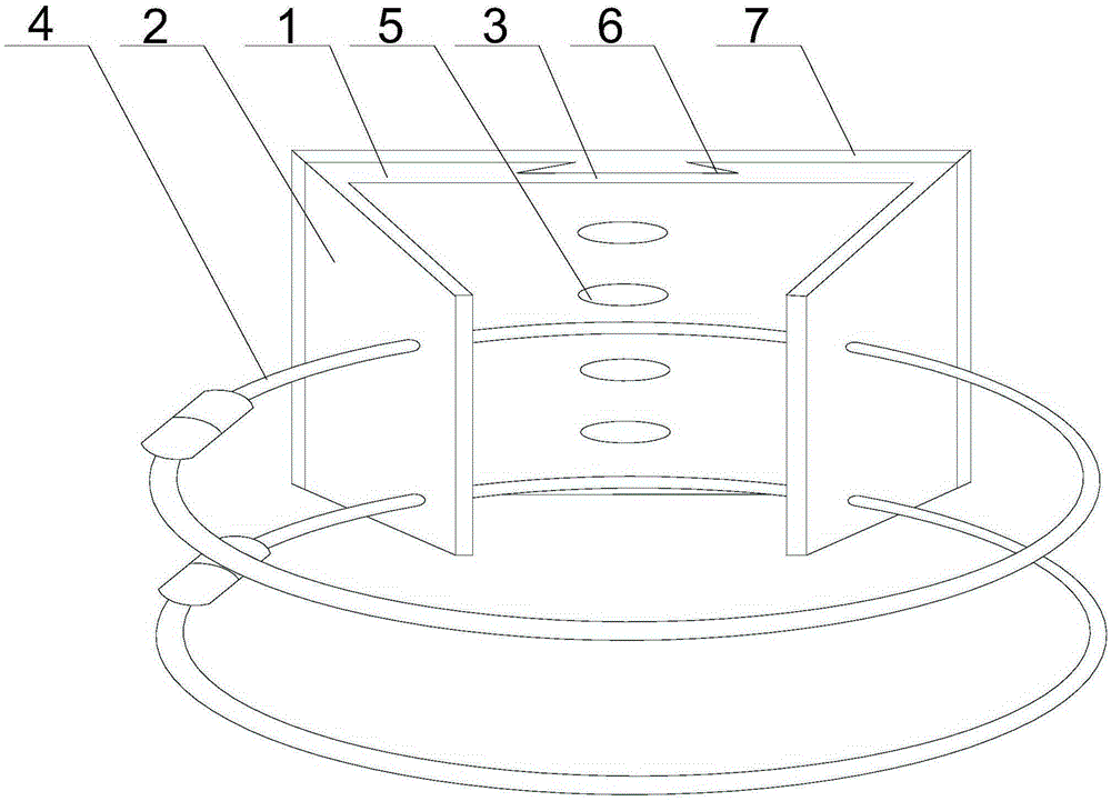
[0019] Such as figure 1 As shown, the present invention includes a dovetail-shaped mounting seat 1 composed of a base plate 3 and two fixing plates 2 arranged at two ends of the base plate 3. A plurality of screw holes 5 are provided in the middle of the base plate 3, and a plurality of the screw holes 5 are provided. The holes 5 are stacked and distributed from top to bottom, and two through holes are opened on the fixed plate 2, and the two clamps 4 respectively pass through the two through holes corresponding to each other on the two fixed plates 2. The back middle part of the bottom plate 3 is provided with a dovetail groove 6, the width of the dovetail groove 6 decreases from top to bottom along the plane of the bottom plate 3, and a connecting plate 7 is provided on the connecting plate 7, which is provided with a matching dovetail groove 6 The connecting plate 7 is provided with a plurality of mounting holes coaxial with the screw holes 5 . When the present invention i...


PUM


Abstract

The invention discloses a placement mechanism for a high-precision equipment working condition monitoring system, which includes a dovetail-shaped mounting seat composed of a bottom plate and two fixing plates arranged at both ends of the bottom plate, and a plurality of screw holes are opened in the middle of the bottom plate , a plurality of the screw holes are stacked and distributed from top to bottom, and two through holes are opened on the fixed plate, and two clamps respectively pass through the two through holes corresponding to each other on the two fixed plates, A dovetail groove is opened in the middle of the back of the bottom plate, the width of the dovetail groove decreases from top to bottom along the plane of the bottom plate, and a connecting plate is also included, and a protrusion matching the dovetail groove is arranged on the connecting plate. There are a plurality of mounting holes coaxial with the screw holes. During use, the two clamps can ensure that there are multiple stress points between the mounting base and the supporting structure, that is, to ensure the stable placement of the monitoring equipment and avoid loosening and other phenomena.

Description

technical field [0001] The invention relates to a monitoring and fixing device, in particular to a placement mechanism of a high-precision equipment working condition monitoring system. Background technique [0002] In the process of processing precision parts, the precision instruments used are often expensive. Therefore, under the premise of ensuring the processing efficiency, how to ensure that the precision instruments are less likely to fail has become the focus of the manufacturing industry. At present, the method adopted is to conduct all-round state monitoring of precision instruments through monitoring equipment, to record its operating status data in real time, and to evaluate the feasibility of continuing to use the precision instruments through data analysis. The most common installation method for monitoring equipment is usually to install a pole-type surveillance camera near the instrument. This installation method uses duckbill brackets and iron wires to fix t...

Claims


Application Information

Patent Timeline
Patent Type & Authority Applications(China)
IPC IPC(8): F16M11/04F16M13/02
CPCF16M11/04F16M13/02F16M2200/00
Inventor 邹杰
Owner 重庆靖画工具有限公司
Why Eureka
Try Eureka