

Data center network system and signal transmission system
A data center network and signal technology, applied in the field of communication, can solve the problems of large number of wiring and difficult maintenance
- Summary
- Abstract
- Description
- Claims
- Application Information
AI Technical Summary
Problems solved by technology
Method used
Image

Examples
Embodiment 1
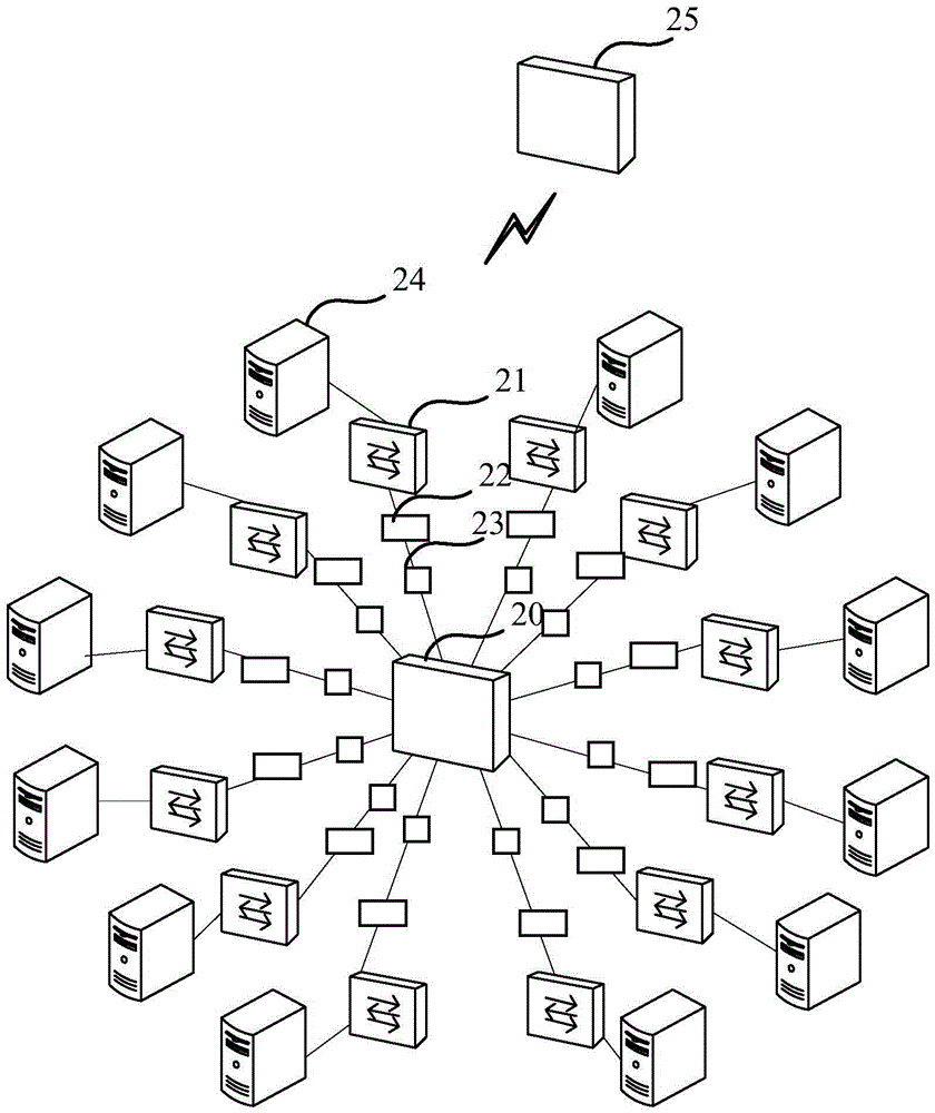
[0065] refer to Figure 2a As shown, it is a schematic diagram of the data center network architecture in the embodiment of the present invention. The data center network system includes a hub device 20, at least two switches 21, a plurality of color light modules 22, at least two multiplexers / demultiplexers 23, and At least two servers 24, of which:
[0066] At least one switch in the at least two switches 21 has a communication connection with at least one server 24, and different input / output ports of each switch 21 have communication connections with different colored light modules 22;
[0067] The different colored light modules 22 that are in communication connection with different input / output ports of each switch 21 are all in communication connection with a multiplexer / demultiplexer 23, wherein different switches 21 communicate with different multiplexers 23 through the color light module 22 / Wave splitter 23 communication connection;
[0068] The at least two switc...
Embodiment 2
[0089] Based on the data center network system described in the first embodiment, for the convenience of description, the following data center network system includes a source server, a source switch, a hub device, a destination switch, and a destination server. The source server and a plurality of color light modules There is a communication connection, all color light modules have a communication connection with a multiplexer / demultiplexer (hereinafter referred to as a source multiplexer / demultiplexer), and the destination server also has a communication connection with multiple color light modules, all color light modules Each optical module has a communication connection with a multiplexer / demultiplexer (hereinafter referred to as the destination multiplexer / demultiplexer), and the source server has a communication connection with the source switch, and the destination server has a communication connection with the destination switch. Both the wave / splitter and the destina...
Embodiment 3
[0133] Based on the data center network system described in the first embodiment, for the convenience of description, the following data center network includes a source server, a source switch, a hub device, a destination switch, and a destination server. Refer to Figure 8 As shown, the source server includes multiple color light modules and a source multiplexer / demultiplexer, all color light modules are connected to the source multiplexer / demultiplexer, and the destination server also includes multiple There are communication connections between each color light module and a destination multiplexer / splitter, all color light modules have communication connections with the destination multiplexer / splitter, and there is a communication connection between the source server and the source switch, and the destination server and the destination The exchange has a communication connection, and the source multiplexer / demultiplexer in the source switch and the multiplexer / demultiplexe...
PUM
 Abstract
Description
Claims
Application Information