
Heart rate detecting device and wearable device

A detection device and heart rate technology, applied in the field of monitoring, can solve the problems of large error in detection results, low reliability, optical sensors are vulnerable to optical fiber, moisture, abnormal skin, etc., and achieve the effect of small error and high reliability

Inactive Publication Date: 2017-06-13
HANGZHOU LIANLUO INTERACTIVE INFORMATION TECH CO LTD
View PDF9 Cites 3 Cited by
  • Summary
  • Abstract
  • Description
  • Claims
  • Application Information

AI Technical Summary

Problems solved by technology

[0005] The embodiment of the present invention provides a heart rate detection device and a wearable device, which realizes the use of bone sensors to obtain the heartbeat frequency of the subject according to the sound wave signal of the heartbeat, and solves the problem that the optical sensor is easily affected by optical fibers, moisture, abnormal skin, etc. Due to the influence of various factors, when using wearable devices for heartbeat frequency detection, the detection results obtained have large errors and low reliability.

Method used


Image

  • Heart rate detecting device and wearable device
  • Heart rate detecting device and wearable device

Examples


Embodiment 1

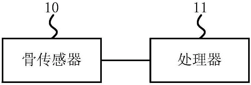
[0038] figure 1 It is a schematic structural diagram of Embodiment 1 of a heart rate detection device according to an embodiment of the present invention, as shown in figure 1 As shown, the heart rate detection device in the embodiment of the present invention may include a bone sensor 10 and a processor 11 .

[0039] Usually, sound conduction is divided into air conduction and bone conduction. Among them, bone conduction refers to the conduction of sound through the bone, so that people can hear the sound through the bone. For example, under the action of bone conduction, you can hear your own voice when you speak, you can hear the sound when you bite your teeth when you cover your ears, you can hear the sound of brushing your teeth when you brush your teeth, and you can hear the sound of your stomach when you are hungry, etc. .

[0040] The frequency of the sound wave signal of each of the above sounds is in the range that can be heard by the human ear, generally 20-16000H...

Embodiment 2

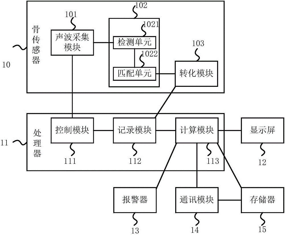
[0053] figure 2 It is a schematic structural diagram of the second embodiment of the heart rate detection device according to the embodiment of the present invention, as shown in figure 2 As shown, the heart rate detection device of the embodiment of the present invention, in figure 1 The technical solutions of the present invention will be further described in more detail on the basis of the illustrated embodiments.

[0054] like figure 2 As shown, in the heart rate detection device of the embodiment of the present invention, the bone sensor 10 may include an acoustic wave acquisition module 101, an analysis module 102, and a conversion module 103, and data interaction between the modules may be realized.

[0055] The sound wave collection module 101 is used to collect the to-be-processed sound wave signal transmitted to the bone sensor 10 itself. For example, the sound wave collection module 101 in the embodiment of the present invention can be realized by using a sound...


PUM


Abstract

The embodiment of the invention provides a heart rate detecting device and a wearable device. The heart rate detecting device comprises a bone sensor and a processor. The bone sensor acquires to-be-processed wave signals conducted to the sensor, analyzes the to-be-processed wave signals to obtain sound wave signals with preset frequency bands and converts the sound wave signals with preset frequency bands into corresponding voice-frequency electric wave signals, wherein the preset frequency bands are set according to the frequencies of the sound wave signals produced by heartbeats under a bond conduction effect. The processor is used for calculating heartbeat frequency according to the voice-frequency electric wave signals. By adopting the technical scheme of the embodiment, the influence of factors such as optical fiber, humidity and abnormal skin conditions can be avoided, obtained detection result errors are smaller, and the reliability is higher.

Description

technical field [0001] Embodiments of the present invention relate to the technical field of monitoring, and in particular to a heart rate detection device and a wearable device. Background technique [0002] With the development of wearable devices and the continuous improvement of people's living standards, the use of various wearable devices such as smart watches and smart bracelets has become more and more popular, and more and more wearable devices have the function of heart rate detection. [0003] Usually, the wearable device is equipped with an optical sensor, and the wearable device can illuminate the capillaries on the skin through LED lights, detect the blood flow speed, and obtain the heartbeat frequency of the wearer. [0004] However, optical sensors are very susceptible to factors such as optical fibers, moisture, and skin abnormalities. As a result, when using wearable devices for heartbeat frequency detection, the detection results obtained have large errors...

Claims


Application Information

Patent Timeline
Patent Type & Authority Applications(China)
IPC IPC(8): A61B5/024
CPCA61B5/024A61B5/02438A61B5/02444
Inventor 陈理张宁宁
Owner HANGZHOU LIANLUO INTERACTIVE INFORMATION TECH CO LTD
Learn More