
Electrically controlled automatic feeding double chamber food utensil device

An automatic supply and diet technology, applied in the direction of therapeutic feeding tubes, etc., can solve the problems of patients who cannot take the initiative to eat and drink, involve energy, and are easy to be choked and choked

Inactive Publication Date: 2017-06-13
牛风节
View PDF0 Cites 2 Cited by
  • Summary
  • Abstract
  • Description
  • Claims
  • Application Information

AI Technical Summary

Problems solved by technology

[0002] At present, it is very difficult for bedridden patients hospitalized in the hospital and bedridden patients at home to complete their own meals. It would be time-consuming, labor-intensive and energy-intensive if the medical staff or accompanying staff often feed the patients, and they cannot leave the patients for a long time, and the patients cannot take the initiative It is also very distressing to eat and drink so that you can’t meet your own needs for eating and drinking at any time. It is very tiring for patients who can turn sideways to keep this position during the process of feeding patients. It is very tiring to feed patients who can only lie flat. It is easy to be choked and choked, and the flow rate of the medical staff or accompanying staff to feed the patient cannot meet the patient's dietary requirements at any time, which can easily cause the patient's unhappiness and cause conflicts between the doctor and the patient. These patients cannot solve their own dietary problems due to long-term bed rest Needs, patients can not choose to drink fluids such as water, fruit juice, milk, soy milk or liquid food at will, resulting in a single nutrition that is not conducive to the recovery of the patient. These problems have always existed and have not been well resolved so far.

Method used


Image

  • Electrically controlled automatic feeding double chamber food utensil device
  • Electrically controlled automatic feeding double chamber food utensil device
  • Electrically controlled automatic feeding double chamber food utensil device

Examples


Embodiment Construction

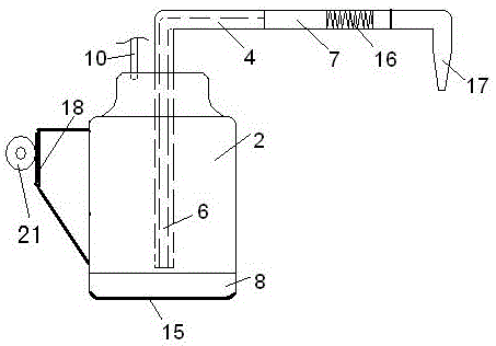
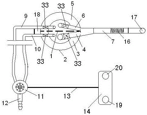
[0005] Electromagnetic valves 33 are respectively arranged in the first suction branch pipe 6, the second suction branch pipe 4, the first flexible telescopic air intake pipe 9 and the second flexible telescopic air intake pipe 10; the driven pulley 26 is arranged on a horizontally movable supporting shell On the rotating shaft in the body 25, the motor 30 is fixed on the horizontally moving support housing 25, and the driving pulley 29 installed in the horizontally moving supporting housing 25 is fixed on its rotating shaft; Belt 27, horizontally moving supporting housing 25 is provided with viewing window 24, supporting sleeve 31 is sleeved on the conveying belt 27, and is fixed on the conveying belt 27 by the positioning bolt 23 screwed on it; positioning plate 32 and supporting sleeve 31 Fixedly connected, the positioning plate 32 and the positioning ring plate 21 are fixed together by positioning fastening bolts 22 . One end of the handle 18 is fixedly connected with the ...


PUM


Abstract

An electronically controlled automatic supply double-cavity eating utensil device belongs to the technical field of electronically controlled automatic supply diet health care devices. At present, the flow rate of medical staff or accompanying personnel feeding food to the patient cannot meet the patient's dietary requirements at any time, which can easily cause the patient's displeasure. The technical solution of this invention is: the driven pulley 26 is arranged on the rotating shaft installed in the horizontally moving supporting shell 25, the motor 30 is fixed on the horizontally moving supporting shell 25, and the rotating shaft is fixed with a Driving pulley 29 in 25; At driving pulley 29 and driven pulley 26, be wound with transmission belt 27. Its advantage is: the use of the device makes the patient feel comfortable during the whole eating process because of satisfying his own eating speed and time requirements, and avoids complicated contradictions between doctors and patients.

Description

technical field [0001] The invention relates to the technical field of an electronically controlled automatic food supply device for health care, in particular to an electronically controlled automatic food supply device with dual chambers. Background technique [0002] At present, it is very difficult for bedridden patients hospitalized in the hospital and bedridden patients at home to complete their own meals. It would be time-consuming, labor-intensive and energy-intensive if the medical staff or accompanying staff often feed the patients, and they cannot leave the patients for a long time, and the patients cannot take the initiative It is also very distressing to eat and drink so that you can’t meet your own needs for eating and drinking at any time. It is very tiring for patients who can turn sideways to keep this position during the process of feeding patients. It is very tiring to feed patients who can only lie flat. It is easy to be choked and choked, and the flow ...

Claims


Application Information

Patent Timeline
Patent Type & Authority Applications(China)
IPC IPC(8): A61J15/00
CPCA61J15/0011A61J15/0026A61J15/0073
Inventor 牛风节
Owner 牛风节
Learn More