Method for stabilizing specific surface area of grinding powder

A specific surface area and grinding technology, which is applied in cement production, grain processing, etc., can solve the problems of manpower and material resources consumption, energy waste, control lag, etc., and achieve the effect of reducing labor intensity, improving control effect, and ensuring smooth operation

Active Publication Date: 2017-06-13
CNBM HEFEI POWDER TECH EQUIP CO LTD
View PDF5 Cites 7 Cited by
  • Summary
  • Abstract
  • Description
  • Claims
  • Application Information

AI Technical Summary

Problems solved by technology

The disadvantages are as follows: First, this manual sampling method requires laboratory personnel to constantly go back and forth between the site and the laboratory in the sampling process, and cycle sampling and testing operations
This artificial control method not only consumes a lot of manpower and material resources, but also cannot output detection data in real time for real-time guidance of central control control
The second is that central control controls production based on the test results every hour, which will inevitably cause a lag in control, which will lead to over-grinding and under-grinding phenomena
Over-grinding refers to the grinding of the incoming powder is too fine, exceeding the specific surface area required by the laboratory, which will cause waste of energy; under-grinding refers to the grinding of the incoming powder is too coarse, which does not meet the specific surface area required by the laboratory , resulting in unqualified finished cement

Method used


Image

  • Method for stabilizing specific surface area of grinding powder
  • Method for stabilizing specific surface area of grinding powder
  • Method for stabilizing specific surface area of grinding powder

Examples


Embodiment Construction

[0030] In order to further explain the features of the present invention, please refer to the following detailed description and drawings of the present invention. The attached drawings are for reference and explanation purposes only, and are not used to limit the protection scope of the present invention.

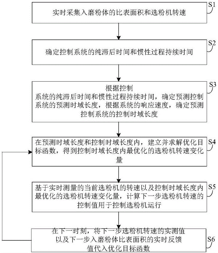
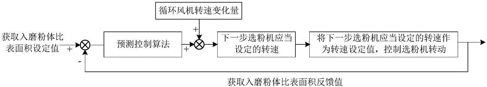
[0031] Such as Figure 1 to Figure 2 As shown, this embodiment discloses a method for stabilizing the specific surface area of ​​the powder body, including the following steps S1 to S6:

[0032] S1, real-time collection of the specific surface area of ​​the powder body and the speed of the separator;

[0033] In practical applications, first use an online particle size analyzer installed in the grinding head to sample the incoming powder in real time, and detect the specific surface area of ​​the incoming powder, and read the speed of the separator in real time from the frequency converter.

[0034] S2. Determine the pure lag time and inertia process time for the speed of the powd...


PUM


Abstract

The invention discloses a method for stabilizing a specific surface area of grinding powder, and belongs to the technical field of cement roller press pregrinding. The method comprises the steps as follows: S1, acquiring the specific surface area of the grinding powder and a rotating speed of a powder concentrator, S2, determining pure lag time and inertia process duration from adjustment of the rotating speed of the powder concentrator to variation of the specific surface area of the grinding powder, S3, determining a prediction time domain and a control time domain, S4, establishing an optimization objective function and solving the optimization objective function to obtain optimal variation quantity of the rotating speed of the powder concentrator within the control time domain, S5, calculating a control value of the rotating speed of the powder concentrator in a next step to control operation of the powder concentrator, and S6, substituting a measured value of the rotating speed of the powder concentrator in a next step and a feedback value of the specific surface area of the grinding powder in a next step into the optimization objective function at a next moment and then circularly performing S4-S5. According to the method, the rotating speed of the powder concentrator is adjusted in real time by variation quantity of the specific surface area of the grinding powder and a rotating speed of a circulating fan, so that the specific surface area of the grinding powder is stabilized near a set value; and smooth operation of equipment is facilitated.

Description

Technical field [0001] The invention relates to the technical field of cement roller press pre-grinding, and in particular to a method for stabilizing the specific surface area of ​​the powder body. Background technique [0002] The purpose of the roller press pre-grinding system is to grind relatively coarse raw materials (mainly clinker, mixed with a certain amount of slag, gypsum and other mixed materials) into relatively fine raw materials. The main equipment of the system is: batching system, conveying system, V-type static air classifier, roller press system, powder separator, circulating fan, high-efficiency cyclone dust collector. [0003] The working process of the system is: the main equipment of the batching system is a quantitative dosing scale. Each raw material has a corresponding dosing scale. The frequency converter of the quantitative dosing scale controls the feeding amount and ratio of various raw materials. The conveying system includes a belt conveyor and a ho...

Claims


Application Information

Patent Timeline
Patent Type & Authority Applications(China)
IPC IPC(8): B02C21/00B02C23/02B02C25/00
CPCB02C21/00B02C23/02B02C25/00Y02P40/10
Inventor 李辉王虔虔许瑞康
Owner CNBM HEFEI POWDER TECH EQUIP CO LTD
Why Eureka
Try Eureka