

Electromagnetic induction type rapid metal melting spray head for 3D metal printer
An electromagnetic induction and printer technology, applied in the field of 3D metal printing, can solve the problems of inability to complete the forming and manufacturing of large metal components, cannot realize fast printing, and cannot be popularized and applied, and achieves fast printing, high cost performance, and high energy conversion efficiency.
- Summary
- Abstract
- Description
- Claims
- Application Information
AI Technical Summary
Problems solved by technology
Method used
Image

Examples
Embodiment Construction
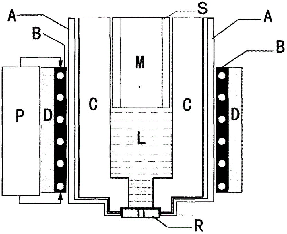
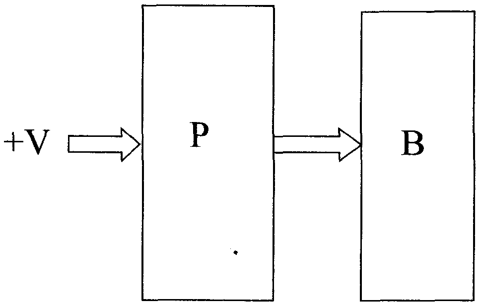
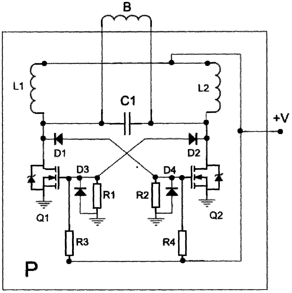
[0023] exist figure 1 Among them, the electromagnetic induction fast metal melting nozzle for 3D metal printer consists of nozzle (R), crucible (C), heat insulation layer (A), medium and high frequency inverter power supply (P), electromagnetic induction coil (B), cooling device (D), the metal to be melted (M) and the feeding device (S). The electromagnetic induction coil (B) surrounds the crucible (C) through the heat insulating layer (A), and the cooling device (D) provides cooling for the electromagnetic induction coil (B) and the medium and high frequency inverter power supply (P), and the medium and high frequency inverter power supply (P) Drive the electromagnetic induction coil (B), so that the metal to be melted (M) in the crucible (C) is rapidly melted by electromagnetic induction to form a metal fluid or liquid (L), and the metal fluid or liquid (L) is sprayed through the nozzle (R) out. As for the ejection method, several mature methods can be used at present, suc...
PUM
 Abstract
Description
Claims
Application Information