

Pipe gallery mold
A mold and pipe gallery technology, which is applied in the direction of molds, manufacturing tools, ceramic molding machines, etc., can solve the problems of high manual vibration requirements, large earthwork excavation volume, and long construction period
- Summary
- Abstract
- Description
- Claims
- Application Information
AI Technical Summary
Problems solved by technology
Method used
Image

Examples
Embodiment Construction
[0026] The present invention will be described in detail below in conjunction with the accompanying drawings. The description in this part is only exemplary and explanatory, and should not have any limiting effect on the protection scope of the present invention. In addition, those skilled in the art can make corresponding combinations of features in the embodiments in this document and in different embodiments according to the descriptions in this document.
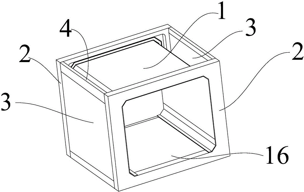
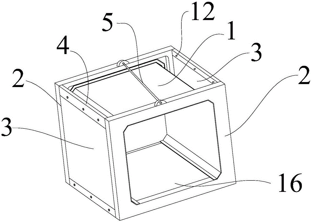
[0027] Embodiments of the present invention are as follows, with reference to figure 1 , a pipe gallery mold, including an inner mold 1 and an outer mold, the outer mold includes a bottom mold 16, two opposite end molds 2 and two opposite side molds, the two ends of the inner mold 1 are respectively Connected with two oppositely arranged end forms 2, the side form and bottom form 16 include a connecting bracket and a concrete prefabricated part 3, and the two oppositely arranged end forms 2 are connected through the conn...
PUM
 Abstract
Description
Claims
Application Information