Embankment structure and construction method

A technology of embankment and geogrid, which is applied to roads, roads, buildings, etc., can solve the problem that the reinforcement has little effect on the lateral displacement of the deep foundation, the strength and stiffness of the reinforcement cannot be fully exerted, and the tensioning membrane of the reinforcement is not enough. Due to the limited transfer capacity of effect loads and other problems, the effects of reducing embankment settlement, reducing uneven settlement and short construction period are achieved.

Pending Publication Date: 2017-06-13
HUAZHONG UNIV OF SCI & TECH
View PDF13 Cites 9 Cited by
  • Summary
  • Abstract
  • Description
  • Claims
  • Application Information

AI Technical Summary

Problems solved by technology

However, the interface friction between the reinforcement and the sand cushion is quite limited. When the limit interface friction is reached, this reinforced cushion cannot effectively limit the lateral displacement of the embankment. According to the research of scholars and experts, the pile-supported reinforcement The rib embankment still has the following disadvantages when solving the construction of expressways in soft soil areas:
[0004] 1) Embankment instability or partial instability may still occur; 2) The lateral displacement of the embankment slope is still obvious; 3) The problem of embankment settlement and uneven settlement is still significant; 4) The lateral displacement of the reinforcement on the deep foundation is limited The effect is not great; 5) The interface friction between the reinforcement and the soil is limited, and the strength and stiffness of the reinforcement cannot be fully utilized; 6) The load transfer capacity of the tensile membrane effect of the reinforcement is limited

Method used


Image

  • Embankment structure and construction method
  • Embankment structure and construction method
  • Embankment structure and construction method

Examples


Embodiment Construction

[0034] The present invention will be described in detail below in conjunction with the accompanying drawings and specific embodiments.

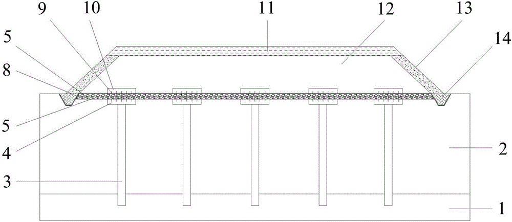
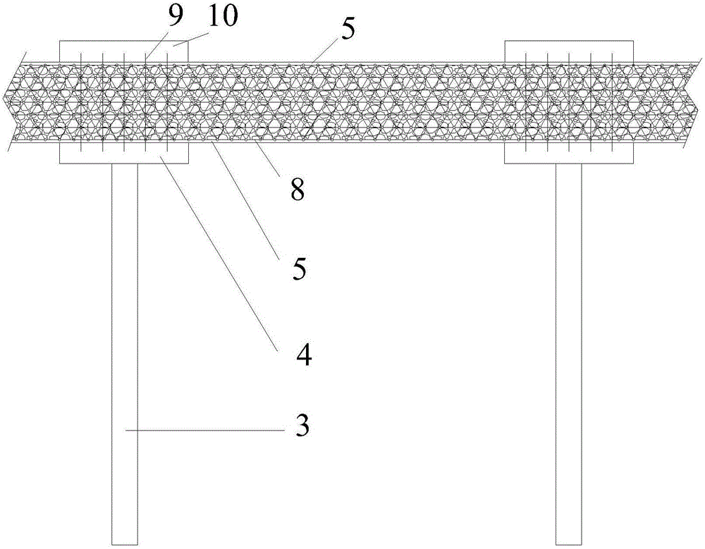
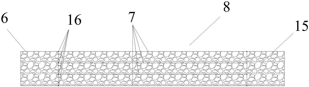
[0035] see figure 1 as well as figure 2 , the present invention provides a kind of embankment structure, comprises bearing layer 1 and soft soil foundation 2 and embankment filling 12 laid on the soft foundation 2; The width of the upper surface of embankment filling 12 is smaller than the surface of soft foundation 2 Width; slope protection is provided between the upper surface of the embankment filling 12 and the soft ground 2; the embankment structure also includes an embankment that is arranged between the soft ground 2 and the embankment filling 12 and extends into the soft ground 2 and the bearing layer 1 The device for preventing embankment settlement; the device for preventing embankment settlement includes pile cap 4, waterproof geotextile 5, microbial modified reinforced cushion 8, pre-embedded steel bar 9, pile cap cover plate 10...


PUM


Abstract

The invention belongs to the technical field of foundation treatment, and relates to an embankment structure and a construction method. The embankment structure comprises a bearing stratum, a soft soil foundation, an embankment filling, and an embankment settlement reducing structure which is arranged between the soft soil foundation and the embankment filling and embedded in the soft soil foundation; the embankment settlement reducing structure comprises pile caps, a piece of waterproof geotechnical cloth, a concrete sealing ditch, a microbial modified reinforced cushion, embedded bars, a pile cap cover plate and a concrete pile group; the concrete pile group consists of m line*n column reinforced concrete thin-walled pipe piles; the pile cap is arranged at the top of each reinforced concrete thin-walled pipe pile; the embedded bar inserted into the pile cap is fixedly arranged on the upper surface of the pile cap; the pile cap cover plate is connected with the pile cap through the embedded bar; the waterproof geotechnical cloth is paved at the top and bottom of the microbial modified reinforced cushion; the embankment filling is arranged on the upper surface of the waterproof geotechnical cloth at the top of the microbial modified reinforced cushion; the waterproof geotechnical cloth is sealed at the bottom of the concrete sealing ditch. The embankment structure and the construction method have the advantages of reasonable structure, convenience in construction and capability of effectively reducing embankment settlement.

Description

technical field [0001] The invention belongs to the technical field of foundation treatment, and relates to an embankment structure and a construction method, in particular to a microbial modified fiber-sand soil-waste tire aggregate-grid reinforced embankment structure and a construction method. Background technique [0002] When building highways and railways in soft soil areas, due to unfavorable engineering factors such as low strength and high compressibility of soft soil, uneven settlement often occurs, which poses a huge challenge to the normal use of roads. [0003] The current common method to solve this problem is to adopt a pile-supported reinforced embankment structure, which consists of the following parts: embankment fill, sand cushion, reinforcement, piles, pile caps, weak foundation and bearing layer. Under the embankment filling load, a soil arch effect is formed between the pile caps, so that most of the embankment load is transferred to the bearing layer t...

Claims


Application Information

Patent Timeline
Patent Type & Authority Applications(China)
IPC IPC(8): E01C3/00E01B2/00
CPCE01B2/00E01C3/04
Inventor 赖汉江郑俊杰崔明娟章荣军曾晨刘辉
Owner HUAZHONG UNIV OF SCI & TECH
Why Eureka
Try Eureka