High-strength concrete-filled steel tube column-beam joint structure and construction method thereof

A technology of concrete filled steel tube and node structure, applied in the direction of building structure, construction, etc., can solve the problems of insufficient strength of building materials, easy torsion of cross-section, labor-intensive and time-consuming, etc., so as to increase the strength and improve the connection strength. , the effect of not easy to reverse

Inactive Publication Date: 2017-06-13
CHANGAN UNIV
View PDF5 Cites 7 Cited by
  • Summary
  • Abstract
  • Description
  • Claims
  • Application Information

AI Technical Summary

Problems solved by technology

In the case of relatively small vertical pressure, in order to ensure good stability and earthquake resistance of the column-beam joint, the cross-section of the steel structure column-beam can be enlarged to make it have a larger radius of gyration, but this will The strength of the building materials will not be fully exerted, and materials will be wasted; the reinforced concrete column beams also need to increase their cross-sections when they bear large loads, but their construction will naturally become more complicated, which is labor-intensive and time-consuming; Although the construction of the structural beam is simple and quick, its section is prone to torsion

Method used


Image

  • High-strength concrete-filled steel tube column-beam joint structure and construction method thereof
  • High-strength concrete-filled steel tube column-beam joint structure and construction method thereof
  • High-strength concrete-filled steel tube column-beam joint structure and construction method thereof

Examples


Embodiment Construction

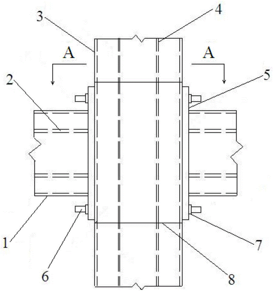
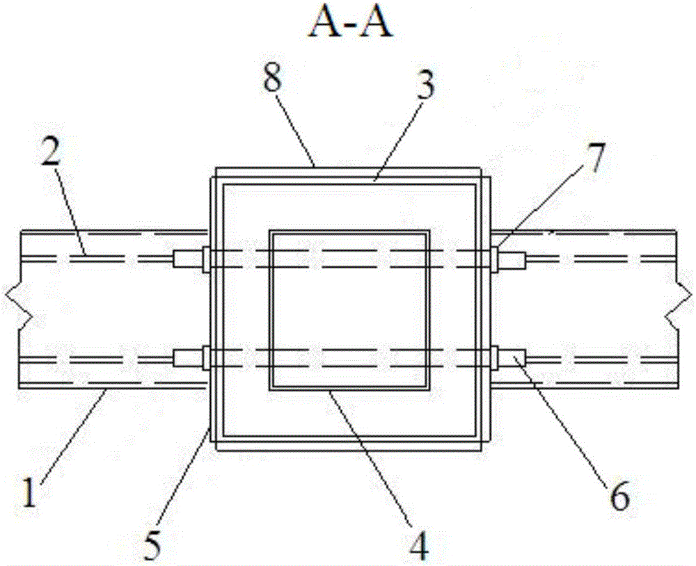
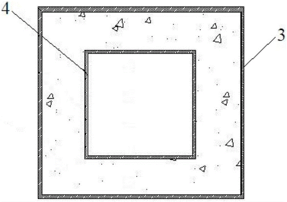
[0030] Such as Figure 1 to Figure 4As shown, the embodiment of the first aspect of the present invention proposes a high-strength steel pipe concrete column-beam node structure, including a pipe column and a pipe beam; the outer wall of the pipe column is the first column square steel pipe 3, and the pipe column The inner side wall of the second column square steel pipe 4, each side wall of the first column square steel tube 3 is parallel to the corresponding side walls on the second column square steel tube 4, and the first column square steel tube 3 and the second column square steel pipe 4 are filled with concrete; the outer wall of the pipe beam is the first beam rectangular steel pipe 1, the inner wall of the pipe beam is the second beam rectangular steel pipe 2, and the first Each side wall of the beam rectangular steel pipe 1 is parallel to the corresponding side walls of the second beam rectangular steel pipe 2, and concrete is filled between the first beam rectangula...


PUM

PropertyMeasurementUnit
thicknessaaaaaaaaaa
thicknessaaaaaaaaaa

Abstract

The invention discloses a high-strength concrete-filled steel tube column-beam joint structure and a construction method thereof. The high-strength concrete-filled steel tube column-beam joint structure comprises a tube column and a tube beam, wherein a first column square steel tube and a second column square steel tube are arranged on the outer side wall and inner side wall of the tube column, and the part between the first column square steel tube and the second column square steel tube is filled with concrete; a first beam rectangle steel tube and a second beam rectangle steel tube are arranged on the outer side wall and inner side wall of the tube beam separately, the part between the first beam rectangle steel tube and the second beam rectangle steel tube is filled with concrete, and beam end plates are welded at two ends of the tube beam; two beam end plates on the tube beam are fixedly connected to the left side and right side of the tube column through nuts and bolts; reinforced steel plates are arranged at the front side and back side of the tube column separately; and two edges of the reinforced steel plates are welded with the edges of the two beam end plates separately. According to the high-strength concrete-filled steel tube column-beam joint structure, the torsion strength and connection strength of the connection joint of the tube column and the tube beam are improved separately. The construction method of the high-strength concrete-filled steel tube column-beam joint structure is used for building the high-strength concrete-filled steel tube column-beam joint structure.

Description

technical field [0001] The invention belongs to the technical field of construction engineering, and in particular relates to a high-strength steel tube concrete column-beam node structure and a construction method for a high-strength steel tube concrete column-beam node structure. Background technique [0002] Reinforced concrete column beams and steel structure column beams are common basic building structures in construction projects. In the case of relatively small vertical pressure, in order to ensure good stability and earthquake resistance of the column-beam joint, the cross-section of the steel structure column-beam can be enlarged to make it have a larger radius of gyration, but this will The strength of the building materials will not be fully exerted, and materials will be wasted; the reinforced concrete column beams also need to increase their cross-sections when they bear large loads, but their construction will naturally become more complicated, which is labor-...

Claims


Application Information

Patent Timeline
Patent Type & Authority Applications(China)
IPC IPC(8): E04B1/30E04B1/58
CPCE04B1/185
Inventor 卜永红杨琦兰官奇王毅红仲继清张又超张坤权登州
Owner CHANGAN UNIV
Why Eureka
Try Eureka