
A container house with energy-saving and thermal insulation functions

A technology for container houses and containers, applied in thermal insulation, passive houses, special buildings, etc., can solve the problems of limited thickness of panels, difficult installation of thermal insulation panels, waste of electric energy, etc., to reduce the influence of water temperature, the overall structure is reliable, Good thermal insulation effect

Active Publication Date: 2019-02-12
中萧建筑科技有限公司
View PDF5 Cites 0 Cited by
  • Summary
  • Abstract
  • Description
  • Claims
  • Application Information

AI Technical Summary

Problems solved by technology

Traditional container hotels have shortcomings such as poor heat insulation and incapable of intelligent control
The traditional container house needs external power supply, which is not suitable for some special areas. Moreover, adding solar panels on the top of the container has a small laying area and is easily damaged by harsh environments such as strong winds.
Because the container is made of iron, the temperature rises very quickly in summer, and the temperature inside the box is very high. The traditional way of adding insulation boards to the outside, the internal air conditioning is difficult to meet the needs, and a lot of electric energy is wasted. This is because the surface of the container is "Wrinkled" surfaces, laying insulation boards and other materials are difficult to install, and in the case of high temperature, it is difficult for the air conditioner to play a corresponding role, and a lot of energy is wasted
Moreover, due to the limited thickness of the panels of the container, it is difficult to achieve the function of sound insulation

Method used


Image

  • A container house with energy-saving and thermal insulation functions
  • A container house with energy-saving and thermal insulation functions
  • A container house with energy-saving and thermal insulation functions

Examples


Embodiment Construction

[0021] The present invention will be further described in detail below in conjunction with the accompanying drawings and embodiments.

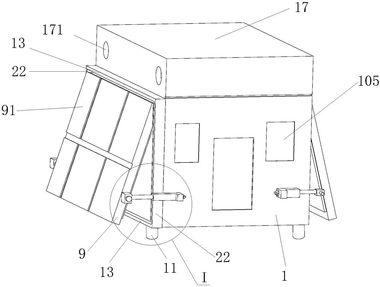
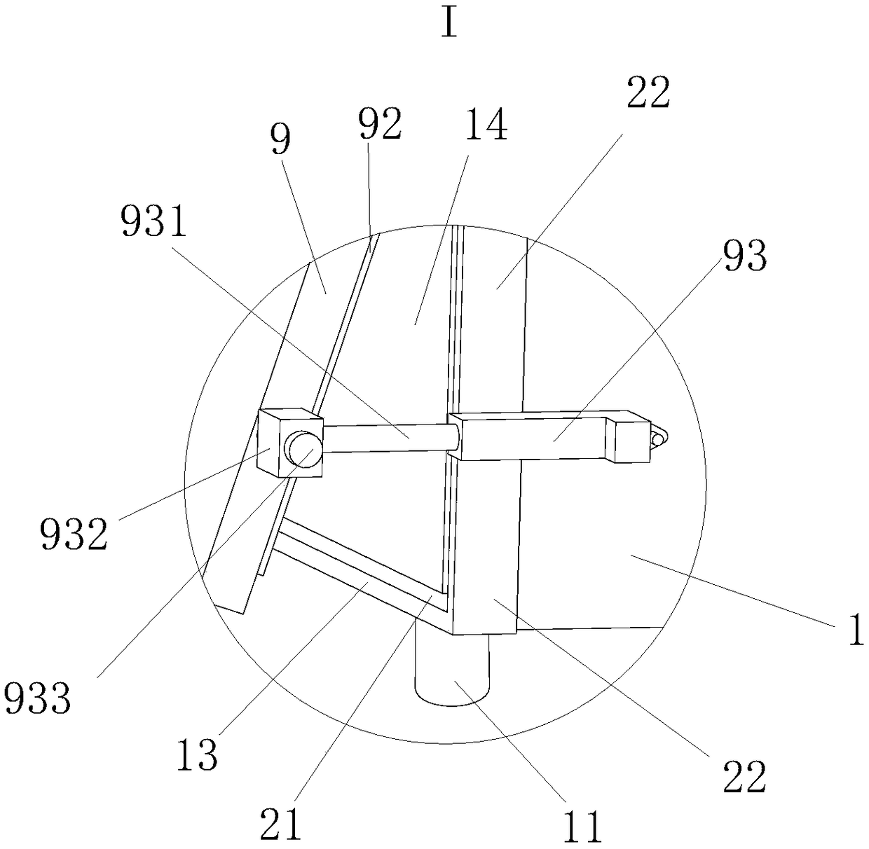
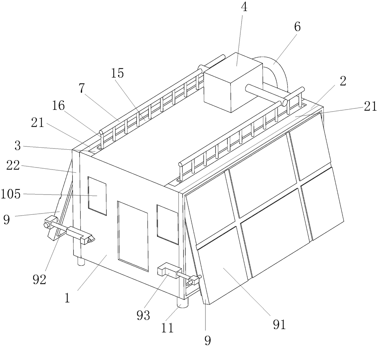
[0022] Such as Figure 1 to Figure 4As shown, a container house with energy-saving and heat-preserving functions includes a container body 1, a fixed plate 2 is arranged on the left and right sides of the container body 1, and the fixed plate 2 and the container body 1 form a vertical cooling sink 3. The upper part of the container body 1 is provided with a water pump 4, and the bottom is provided with a water tank 5. The water tank 5 is provided with an electric heater 51. The water pump 4 and the water tank 5 are connected through a water suction pipe 6. The water pump 4 is provided with a water outlet pipe 7, and the water outlet pipe 7 is connected to the upper end of the cooling sinker 3, and the bottom of the cooling sinker 3 is provided with a water outlet hole 8, and the water outlet hole 8 is connected to the inside of the water tank ...


PUM


Abstract

The invention relates to the field of container recycle and discloses a container house with energy-saving and heat preservation functions. The left side face and the right side face of a container body (1) are provided with fixing plates (2). A cooling sunken groove (3) is defined by the fixing plates (2) and the container body (1). The upper portion of the container body (1) is provided with a water pump (4), and the bottom of the container body (1) is provided with a water tank (5) which is provided with an electric heater (51). The water pump (4) is connected with the water tank (5) through a water suction pipeline (6). Mounting plates (22) are fixed to an outer fixing plate (21). Mobile plates (9) are arranged between the mounting plates (22). The outer side faces of the mobile plates (9) are provided with solar power generation panels (91), and the inner side faces of the mobile plates (9) are provided with heat preservation plates (92). The mobile plates (9) are controlled through electric cylinders (93). The container house has the advantages such as good heat preservation performance, can provide a power supply for the container house, is high in power generation efficiency and meanwhile has the functions such as sound insulation and remote control.

Description

technical field [0001] The invention relates to the field of container reuse, in particular to a container house with energy-saving and heat-preserving functions. Background technique [0002] With the development of social economy, land resources are becoming more and more tense. Moreover, during the construction process of traditional buildings, a lot of energy is wasted. At the same time, the buildings are immovable, which brings constraints to people. Therefore, green and energy-saving residential houses are becoming more and more popular. As an important tool for freight transportation, containers are discarded as scrap iron, wasting a lot of resources, and also have an impact on the environment. The transformation and construction of containers saves a lot of cost for hotels used for living, and container hotels are mobile. It provides more possibilities for people's living places. Traditional container hotels have shortcomings such as poor heat insulation and inca...

Claims


Application Information

Patent Timeline
Patent Type & Authority Patents(China)
IPC IPC(8): E04B1/344E04H1/12E04B1/76
CPCE04B1/76E04H1/12E04H2001/1283Y02A30/00Y02B30/90
Inventor 王学超
Owner 中萧建筑科技有限公司
Learn More