Hand-eye calibration method for laser line structured light sensor

A structured light sensor and hand-eye calibration technology, applied in the field of sensor calibration, can solve the problems of lack of calibration results, accurate calibration process is simple and time-saving, parameter distribution has a great influence on the results, and it is difficult to maintain accuracy, etc., to achieve shortened calibration time and high practicality Value, good quality results

Active Publication Date: 2017-06-13
SHANGHAI JIAO TONG UNIV
View PDF7 Cites 36 Cited by
  • Summary
  • Abstract
  • Description
  • Claims
  • Application Information

AI Technical Summary

Problems solved by technology

Obviously, the above requirements are harsh. Keeping the laser at the same point in different poses is time-consuming and labor-intensive, and it is difficult to maintain accuracy.
[0008] Another calibration method using a plane template, the robot measures the plane at different positions and attitudes, records the corresponding robot pose parameters, and uses the least squares method to fit the plane to solve the calibration problem of the laser displacement sensor. This method is easy to operate, but The parameter distribution has a great influence on the result, and more points are required for fitting the plane, which is time-consuming
[0009] To sum up, the laser line structured light sensor currently lacks a method with accurate calibration results and a simple and time-saving calibration process.

Method used


Image

  • Hand-eye calibration method for laser line structured light sensor
  • Hand-eye calibration method for laser line structured light sensor
  • Hand-eye calibration method for laser line structured light sensor

Examples


Embodiment

[0085] The method based on linear constraints is used to calibrate the hand-eye of the robot with the laser line structured light sensor at the end. The robot used in the experiment is the Motoman ssa2000 six-degree-of-freedom robot produced by Yaskawa, and the sensor is the LJ_G200 produced by KEYENCE.

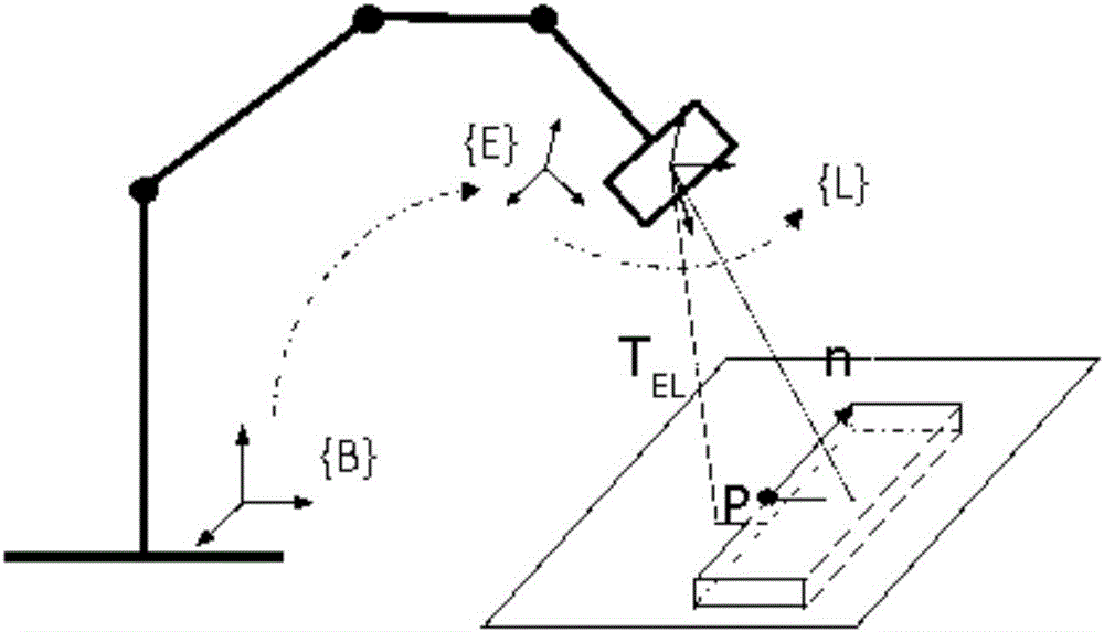
[0086] The schematic diagram of the robot's hand-eye calibration model with the sensor at the end is as follows: figure 1 , the base coordinate system {B} is established on the base of the robot, the end coordinate system {E} is established on the end link, and the sensor coordinate system {L} is established on the sensor, where the origin of the coordinate system {L} is at the laser exit point, and the Z axis The direction coincides with the direction of the bisector of the outgoing laser angle, the X axis is perpendicular to the Z axis on the light plane, and the Y axis is perpendicular to the light plane. The homogeneous transformation matrix of {E} relative to {B} is deno...


PUM


Abstract

The invention provides a hand-eye calibration method for a laser line structured light sensor. The hand-eye calibration method includes the steps that a sensor coordinate system is established on the sensor, a structured light stripe is generated from a structured light plane projected by a mid-laser device of the sensor to a target, the pose of a robot is adjusted, the stripe and a straight line on a calibration template are intersectant to form feature points, and a pose parameter of the robot and output data of the sensor of this moment are recorded; outputting of the sensor is combined with geometrical parameters of the sensor, and three-dimensional coordinates, under the sensor coordinate system, of all the points on the laser stripe can be obtained; the feature points generated when the stripe and the straight line on the calibration template are intersectant are extracted. The process is repeated, N sets of different robot pose parameters and the feature points corresponding to all the parameters are obtained, the calibration problem is converted into the least square problem through N sets of data collected under a constraint of space straight lines, and the problem is solved through the optimization algorithm. The hand-eye calibration method is simple and convenient and easy to conduct, the position and the pose are accurately controlled, the efficiency is high, the quality is good, and the hand-eye calibration method has the high practical value.

Description

technical field [0001] The invention relates to the technical field of sensor calibration, in particular to a hand-eye calibration method for a laser line structured light sensor. Background technique [0002] It is the main development trend of robots to install non-contact sensors (laser displacement sensors, laser scanners, cameras, etc.) on the connecting rod at the end of the robot to form an intelligent robot with a certain perception of the environment without touching the workpiece. To realize this function, the position and direction of the sensor relative to the end link need to be calibrated in advance, and this process is called hand-eye calibration. In order to perceive the environment more effectively, accurate calibration is required. [0003] At present, the methods and research of robot hand-eye calibration focus on industrial cameras. There are few methods for hand-eye calibration of the laser ranging sensor installed at the end of the robot, including th...

Claims


Application Information

Patent Timeline
Patent Type & Authority Applications(China)
IPC IPC(8): G01B11/00
Inventor 郑健张轲朱晓鹏罗志锋王志刚陈易新
Owner SHANGHAI JIAO TONG UNIV
Why Eureka
Try Eureka