
Turbo shaft engine test bench for aviation

A turboshaft engine and test bench technology, which is applied in the direction of engine testing, machine/structural component testing, and measuring devices, can solve problems such as poor reliability and inability to guarantee rigidity, and achieve small footprint, stable transmission, and simplified transmission Institutional Effects

Pending Publication Date: 2017-06-13
KUNSHAN HANGLI AIRBORNE EQUIP
View PDF4 Cites 15 Cited by
  • Summary
  • Abstract
  • Description
  • Claims
  • Application Information

AI Technical Summary

Problems solved by technology

However, this utility model still belongs to the column support, and neither the column support nor the test bench of the utility model directly supports the engine, so the direct support structure of the engine cannot be guaranteed to have sufficient rigidity, and the reliability is poor
[0006] In the driving system of the aero-engine test bench, the utility model with the application number CN201620059118.6 discloses a multi-factor coupling vibration control comprehensive test bench for the aero-engine. The drive system described in the utility model includes a first drive motor, a first Shaft, the second drive motor and the second coupling; the first drive motor in the drive system is connected through the first coupling to transmit power to the low-pressure rotor system of the aero-engine body, and the second drive of the drive system The motor transmits power to the high-pressure rotor system of the aero-engine body through the second coupling and the accessory transmission system in the aero-engine body; The drive motor of the new drive system is directly connected with the low-pressure rotor and high-pressure rotor of the engine body through a coupling, and the engine can only be driven by the electric motor. There is only one transmission mode, which cannot meet the three test modes used in the teaching of aviation turboshaft engines. needs

Method used


Image

  • Turbo shaft engine test bench for aviation
  • Turbo shaft engine test bench for aviation
  • Turbo shaft engine test bench for aviation

Examples


Embodiment Construction

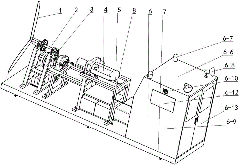
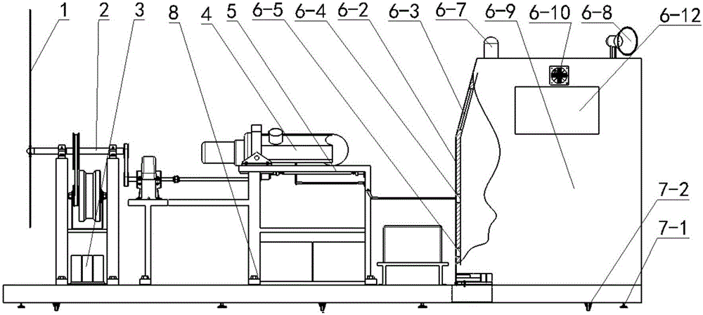
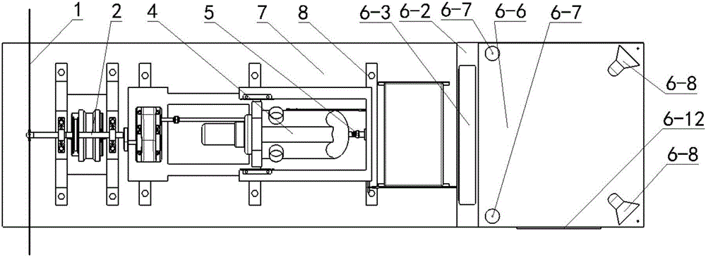
[0096] Such as Figure 1 ~ Figure 4 As shown, the present invention includes a propeller 1, a drive system 2, a control system 3, an engine 4, a support structure 5, a control room 6 and a base 7;

[0097] Such as Figure 1 ~ Figure 4 , Figure 8 and Figure 9As shown, the drive system 2 includes a frame 2-1, a motor mounting plate 2-2 is welded on the frame 2-1, a motor bracket 2-3 is welded on the motor mounting plate 2-2, and a motor mounting plate 2-3 is welded on the frame 2-1. The right side of 2-1 is also provided with the third column 5-3 shared with support structure 5 and reducer support plate 5-9, motor 2-4 is installed on motor support 2-3, on frame 2-1 The top is equipped with a first bearing seat 2-10 and a second bearing seat 2-16, and a ball bearing 2-18 is installed in the first bearing seat 2-10 and the second bearing seat 2-16, and two ball bearings 2 Main shaft 2-11 is installed in -18, the fourth pulley 2-13 is installed on the main shaft 2-11, the sec...


PUM


Abstract

The invention provides a turbo shaft engine test bench for aviation, and aims at overcoming the defects that the turbo shaft engine test bench in the prior art is poor in stability, low in locating accuracy and low in security, only has one transmission mode, the problem of test run of a turbo shaft engine for aviation under the condition of the load cannot be solved. The turbo shaft engine test bench is characterized by comprising a drive system, a control system, an engine, a support structure and a control room, wherein a four-point locating support structure of the engine is formed by front and back two locating lugs, a horizontal locating support shaft and a vertical locating support shaft; and an integrated console integrating control, display and data processing is arranged in the control room. The turbo shaft engine test bench has the beneficial effects that the turbo shaft engine test bench is provided with the load, is high in locating support accuracy and high in vibration resistance; vertical output is changed into axial output by the drive system; the transmission is stable and the occupied space is small; miniaturization of the turbo shaft engine test bench for aviation is achieved; the turbo shaft engine test bench has three modes of hot test run, cold test run and simulated test run; the teaching efficiency is improved; the security during test run is ensured; abrasion of the engine is reduced; and the teaching cost is reduced.

Description

technical field [0001] The invention belongs to the technical field of aero-engine test benches, in particular to an aero turboshaft engine test bench suitable for teaching. Background technique [0002] The test run of the engine on the ground bench is generally used to check whether the performance parameters of the overhauled or overhauled engine meet the release standards for safe flight. It is an essential and important step before the product is delivered. It is also used in aviation colleges In teaching teaching aids, to train professional and technical personnel. During the test run of the engine on the ground bench, the vibration is large, the noise is high, and the interference signals are generated, all of which put forward higher requirements for the test run inspection and testing system. [0003] The invention application with the patent application number CN201510846701.1 discloses a piston-type aero-engine test bench, including an engine mounting frame, a te...

Claims


Application Information

Patent Timeline
IPC IPC(8): G01M15/02G09B25/02
CPCG09B25/02G01M15/02
Inventor 杨明卜铁孙志鑫孙玉玺
Owner KUNSHAN HANGLI AIRBORNE EQUIP
Learn More