Voltage sensor suitable for field measurement of transformer substation

A voltage sensor and on-site measurement technology, applied in the direction of measuring electrical variables, measuring devices, instruments, etc., can solve the problems of inapplicable electronic voltage transformer calibration, ferromagnetic resonance caused by live connection to the power grid, and large equipment size and weight and other issues to achieve the effect of improving reliability and economy, avoiding loss and inconvenience, and improving accuracy and reliability

Pending Publication Date: 2017-06-13
国网甘肃省电力公司金昌供电公司 +3
View PDF7 Cites 2 Cited by
  • Summary
  • Abstract
  • Description
  • Claims
  • Application Information

AI Technical Summary

Problems solved by technology

[0003] At present, some scholars have carried out relevant research on the online calibration of electronic transformers. Although they have achieved certain success, there are still many problems: Chinese patent "CN102645643A" designed an online calibration system for electronic voltage transformers. However, due to the use of traditional electromagnetic voltage transformers as standard transformers, ferromagnetic resonance may occur when connected to the power grid with electricity, and there are certain safety hazards. When the voltage level is high, the size and weight of the equipment will also change. Large, not conducive to the use of online calibration; Chinese patent "CN102401889A" proposed an online calibration method for electronic current transformers, but this method is not suitable for electronic voltage transformers

Method used


Image

  • Voltage sensor suitable for field measurement of transformer substation
  • Voltage sensor suitable for field measurement of transformer substation
  • Voltage sensor suitable for field measurement of transformer substation

Examples


Embodiment Construction

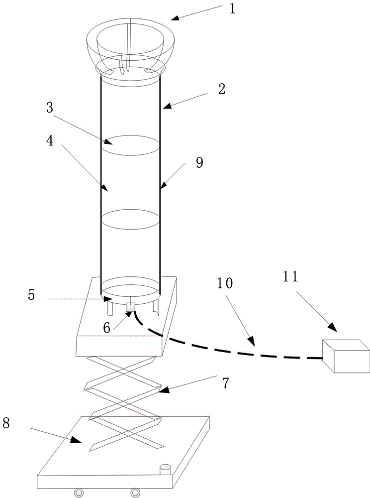
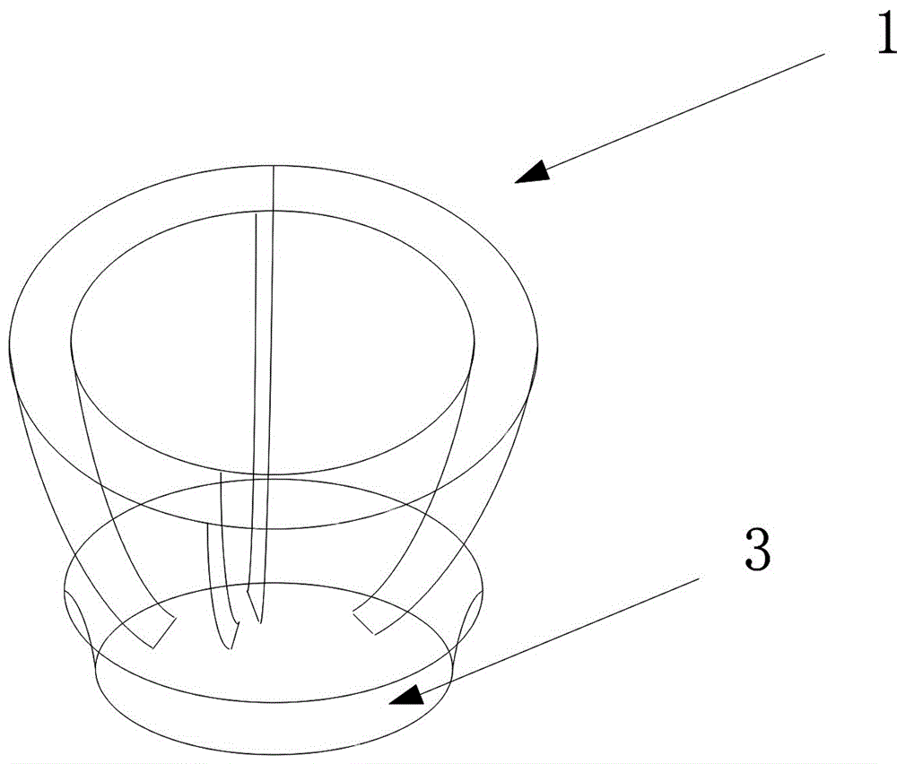
[0025] Such as Figure 1~Figure 5 As shown, a voltage sensor suitable for on-site measurement in substations includes a voltage equalizing ring 1 , a primary voltage sensing unit 2 , a collection and transmission unit 6 , and a lifting platform 7 .

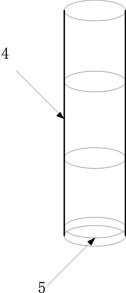
[0026] The primary voltage sensing unit 2 uses a parallel plate capacitor to form a high-voltage capacitor 4 and a low-voltage capacitor 5, which are filled with air to form a gas capacitor, which has good insulation, and its volume and weight do not change much when the voltage level increases , very suitable for on-site verification. The high-voltage capacitor 4 is composed of three gas capacitors with three pole spacings of 1.5m; the low-voltage capacitor 5 is composed of one gas capacitor with a pole spacing of 0.04m; the high-voltage capacitor 4 and the low-voltage capacitor 5 are divided in series. When the high-voltage transmission circuit is 220kV, the voltage signal U generated in the low-voltage capacitor 5 1 It is abo...


PUM


Abstract

A voltage sensor suitable for field measurement of a transformer substation comprises a grading ring, a primary voltage sensing unit, an acquisition transmission unit and an elevating platform. According to the voltage sensing unit, a high-voltage capacitor and a low-voltage capacitor are composed of parallel-board capacitors; and high-voltage capacitor and the low-voltage capacitor are filled with air, thereby forming a gas capacitor. The high-voltage capacitor is composed of three gas capacitors with polar distances of 1.5m. The low-voltage capacitor is composed of one gas capacitor with polar distance of 0.04m. The high-voltage capacitor and the low-voltage capacitor realize voltage shunting through serial connection. The acquisition transmission unit is arranged below the low-voltage capacitor. Furthermore the acquisition transmission unit is connected with the low-voltage capacitor through an optical fiber. The acquisition transmission unit is obtained through successively connecting a signal processing module, an A/D conversion module and an FPGA. A signal which is output from the acquisition transmission unit is transmitted to a subsequent processing terminal through the optical fiber. The voltage sensor has advantages of realizing live verification to an electronic voltage transformer, shortening verification period, simplifying operation step, preventing loss caused by power failure, and improving accuracy and reliability in online verification of the electronic voltage transformer.

Description

technical field [0001] The invention relates to a voltage sensor suitable for on-site measurement of a substation, and relates to the field of power system measurement. Background technique [0002] With the development of digital substations and smart grids, traditional transformers cannot meet the development requirements of power grids due to their shortcomings such as ferromagnetic resonance, poor insulation, and narrow dynamic range. In order to meet the development needs of high-capacity and high-voltage levels, electronic voltage transformers with the advantages of no magnetic saturation, high measurement accuracy, and wide frequency response have received more and more attention, and have become the main development direction of power system measurement. However, in actual operation, the accuracy of the electronic voltage transformer is more serious, so it is necessary to verify its accuracy. Most of the traditional transformer calibration methods are offline calibr...

Claims


Application Information

Patent Timeline
Patent Type & Authority Applications(China)
IPC IPC(8): G01R35/02
CPCG01R35/02
Inventor 陈建鹏张国荣张宏伟任灵姚斌张宝王晓林王志国李春亮李振华
Owner 国网甘肃省电力公司金昌供电公司
Why Eureka
Try Eureka