Cable entry insulating ground excess cable box on transformer substation

A technology for substations and cable boxes, applied in light guides, optics, instruments, etc., can solve problems such as poor insulation and unreliable grounding, achieve good grounding, avoid the risk of climbing poles, and facilitate maintenance

Active Publication Date: 2017-06-13
WUHAN NEW ENERGY TECH DEV
View PDF6 Cites 4 Cited by
  • Summary
  • Abstract
  • Description
  • Claims
  • Application Information

AI Technical Summary

Problems solved by technology

[0005] The purpose of the present invention is to solve the shortcomings of poor insulation and unrelia...

Method used


Image

  • Cable entry insulating ground excess cable box on transformer substation
  • Cable entry insulating ground excess cable box on transformer substation
  • Cable entry insulating ground excess cable box on transformer substation

Examples


Embodiment Construction

[0029] The technical solutions in the embodiments of the present invention will be clearly and completely described below with reference to the accompanying drawings in the embodiments of the present invention. Obviously, the described embodiments are only a part of the embodiments of the present invention, but not all of the embodiments.

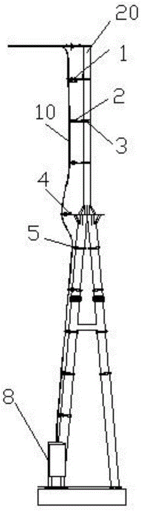
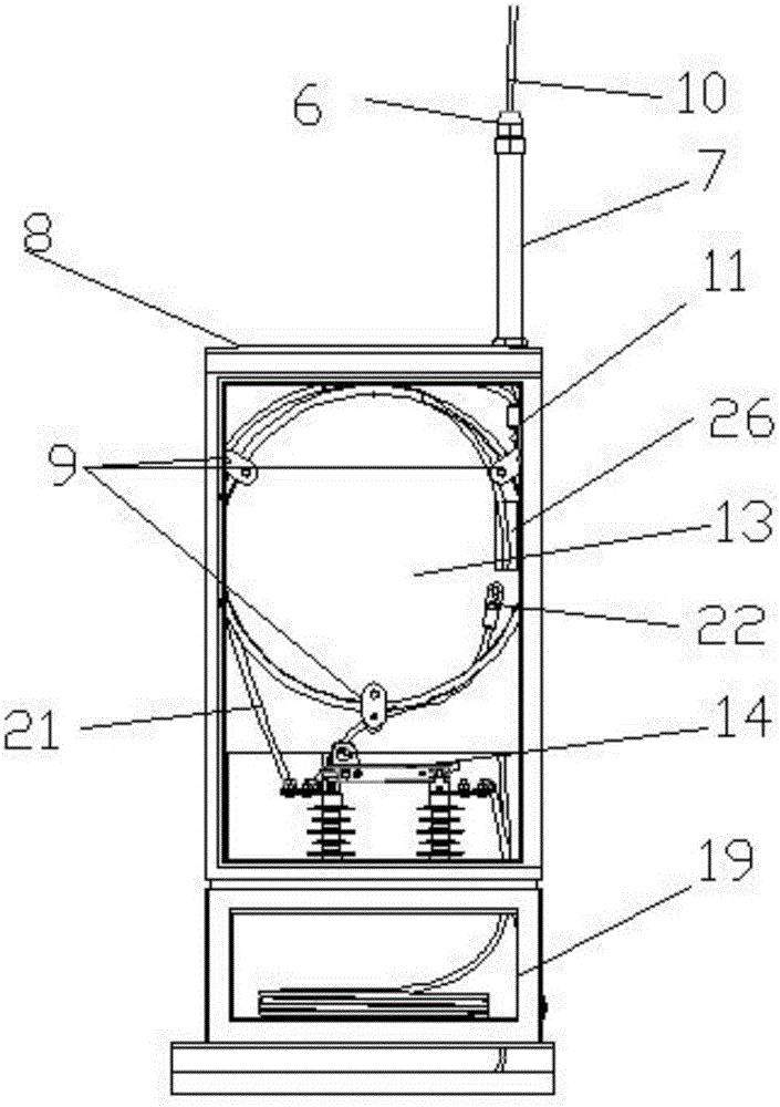
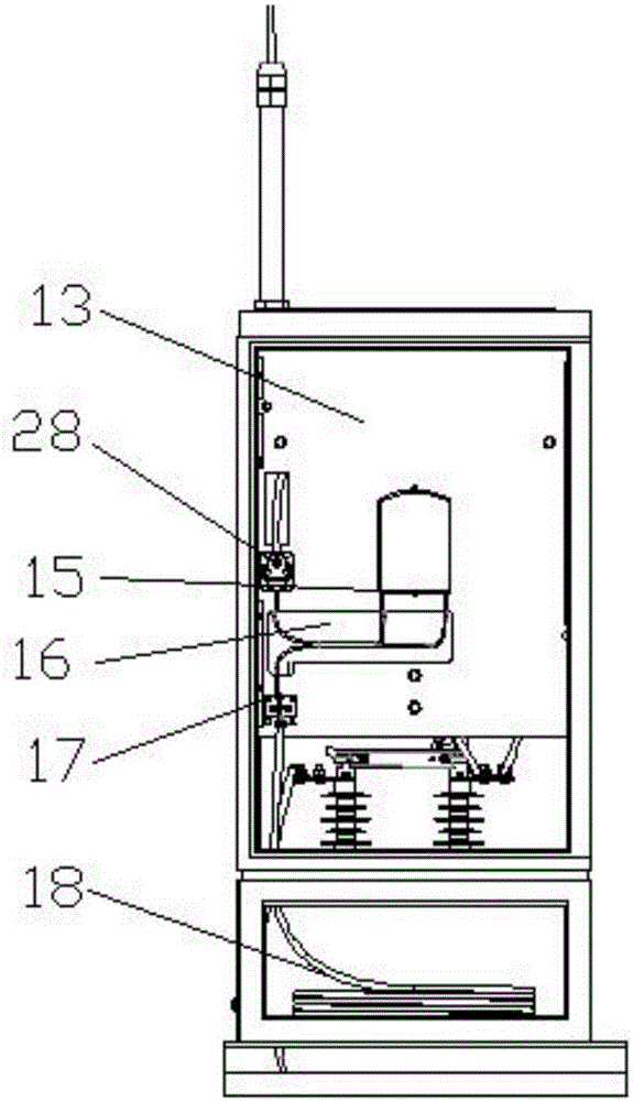
[0030] refer to Figure 1-8 , a substation upper cable insulation grounding residual cable box, including a box body 8 and an OPGW optical cable drop device. At the bottom of the frame 20, the optical cable drop device includes an OPGW voltage limiting device 1 and a fixing device. The OPGW voltage limiting device 1 is arranged on the top of the portal frame 20, and a pin insulator 2 is installed on the fixing device. On the insulator 2 and the voltage limiting device 1, the voltage limiting device 1 is connected with a first ground wire 12, and the other end of the first ground wire 12 is connected with the gate frame 20; Electricity for ...


PUM


Abstract

The invention relates to the technical field of excess cable boxes, in particular to a cable entry insulating ground excess cable box on a transformer substation. The cable entry insulating ground excess cable box on the transformer substation comprises a box body and an OPGW optical cable downward leading device, an OPGW optical cable enters the box body from the top of a door-shaped frame, through the OPGW optical cable downward leading device, the box body is arranged at the bottom of the door-shaped frame, the optical cable downward leading device comprises an OPGW voltage limiting device and a fixing device, the OPGW voltage limiting device is arranged at the top of the door-shaped frame, and the fixing device is provided with a needle-type insulator. The able entry insulating ground excess cable box on the transformer substation is reliable in insulation and good in grounding performance, effectively solves the hidden danger that the OPGW optical fiber is ablated and the strand is broken, and moreover, the box is convenient to construct and easy to maintain, and has good application value.

Description

technical field [0001] The invention relates to the technical field of redundant cable boxes, in particular to an insulated floor-to-ceiling redundant cable box for upper feed cables in a substation. Background technique [0002] At present, some power companies use the portal frame to lead down the OPGW in the substation. The OPGW optical cable is grounded at a position 1.5 meters above the ground using parallel trench clamps, grounding wires and a special grounding device for the portal frame. φ50mm hot-dip galvanized steel pipe, OPGW optical cable needs to pass through the insulating sleeve before passing through the hot-dip galvanized steel pipe into the cable trench to ensure that the OPGW optical cable is insulated from the galvanized steel pipe, the door frame, and the earth. The OPGW optical cable enters the redundant cable box on the ground from the cable trench. The OPGW optical cable reel is stored on the metal cross on the front of the redundant cable box, the or...

Claims


Application Information

Patent Timeline
IPC IPC(8): G02B6/44
CPCG02B6/4446G02B6/4452
Inventor 余涛
Owner WUHAN NEW ENERGY TECH DEV
Why Eureka
Try Eureka