Multichannel power correction control device and method

A time-controlled, multi-channel technology, applied in electrical program control, program control in sequence/logic controllers, etc., can solve the problem of inability to achieve multi-print head power calibration time control, etc., to improve accuracy and real-time performance, Improve real-time performance and improve efficiency

Active Publication Date: 2017-06-13
杭州朔天科技有限公司 +1
View PDF6 Cites 0 Cited by
  • Summary
  • Abstract
  • Description
  • Claims
  • Application Information

AI Technical Summary

Problems solved by technology

[0005] The existing printing control unit basically only supports the power calibration time control

Method used


Image

  • Multichannel power correction control device and method
  • Multichannel power correction control device and method
  • Multichannel power correction control device and method

Examples


Embodiment Construction

[0022] The present invention will be further described below in conjunction with accompanying drawing.

[0023] The invention mainly aims at multi-channel power calibration time control, and proposes a real-time, efficient and accurate control method which saves hardware resources.

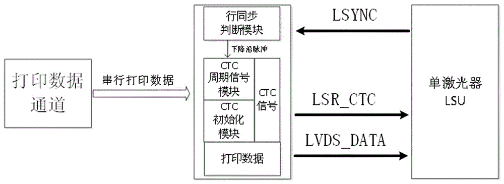
[0024] Such as Figure 4 As shown, the multi-channel power calibration time control unit of the present invention ( Figure 4 shown in the dashed box), including LSU enabling and line synchronization processing module, CTC1 signal module, n-1 signal splitting control module, n-1 signal aliasing generator module, and n-1 automatic cycle dialing control module.

[0025] The LSU enabling and line synchronization processing module includes an LSU enabling unit, a line synchronization signal detection unit, a configuration information unit and an edge pulse generator.

[0026] The enabling of the LSU enabling unit is the starting point for all subsequent modules to work. The configuration informati...


PUM


Abstract

The invention discloses a multichannel power correction control unit. An LSU enabling and line synchronous processing module can enable an LSU and various functional modules; a CTC1 signal module can generate CTC1 signals in an initialization stage and a normal work period according to configuration information, and can also transmit control information to an (n-1) path signal splitting and controlling module and receive initialized completed marks of an (n-1) path signal aliasing generator module; the (n-1) path signal splitting and controlling module receives and analyzes a preceding stage control signal, generates (n-1) path signal splitting and controlling information according to the analyzed information and transmits the (n-1) path signal splitting and controlling information to the next stage; the (n-1) path signal aliasing generator module receives a pulse signal sent from the (n-1) path signal splitting and controlling module, generates an aliasing signal and transmits the signal to the next stage; an (n-1) path automatic cycle dial-up control module receives a cycle counter transmitted by the (n-1) path signal splitting and controlling module.

Description

technical field [0001] The invention belongs to the field of laser printers, in particular to a multi-channel power correction time control device and method. Background technique [0002] At present, the LSU control unit with single laser is mainly used in the market. With the improvement of the production and manufacturing process of lasers, the laser scanning unit (LSU) of multiple lasers is ready for production. The main components of the laser emitting part of the LSU are the laser and the power correction unit. When printing the output data of the data module, the data '1' makes the laser emit light, and the data '0' makes the laser not emit light; when the laser emits light for a period of time, the power needs to be recalibrated. The time point of calibration is very important. The interference print data module controls the laser. [0003] The most important part of the control device of the existing laser emitting part of the LSU is the print head power calibrat...

Claims


Application Information

Patent Timeline
IPC IPC(8): G05B19/04
CPCG05B19/04
Inventor 陈伟祥张晓旭
Owner 杭州朔天科技有限公司
Why Eureka
Try Eureka