Automatic cutting and separating equipment for photovoltaic cells

A photovoltaic cell and separation equipment technology, applied in photovoltaic power generation, circuits, electrical components, etc., can solve the problems of mobile stage movement accuracy error, affecting laser cutting accuracy, poor cutting accuracy stability, etc., to reduce manpower cost and production cost, increase output and production efficiency, and enhance market competitiveness

Active Publication Date: 2017-06-13
OPES SOLUTIONS (CHANGZHOU) CO LTD FACTORY
View PDF7 Cites 5 Cited by
  • Summary
  • Abstract
  • Description
  • Claims
  • Application Information

AI Technical Summary

Problems solved by technology

However, this cutting process has the problems of slow cutting speed and unstable cutting accuracy.
In general, the stage carrying the cells is connected with a driving device so that it can move in the XY direction, but due to the limitations of the structure of the driving device, such as screws, guide rails, etc., and the reciprocating motion of the mobile stage requires considerable Movement time, which affects the movement speed of the stage
As a result, it is difficult to shorten the cutting process, resulting in low production capacity
In addition, there is a certain degree of error in the movement accuracy of the mobile carrier, which will directly affect the accuracy of laser cutting, resulting in poor stability of cutting accuracy
[0006] In view of this, it is necessary to provide a technology that is different from the previous technology that requires a lot of manpower, high labor costs and slow cutting speed, so as to overcome the above disadvantages, and at the same time take into account the needs of improving efficiency, improving yield and reducing labor costs.

Method used


Image

  • Automatic cutting and separating equipment for photovoltaic cells
  • Automatic cutting and separating equipment for photovoltaic cells
  • Automatic cutting and separating equipment for photovoltaic cells

Examples


Embodiment Construction

[0027] In order to make the above-mentioned and other purposes, features, and advantages of the present invention more clearly understood, a preferred embodiment is specifically cited below, together with the accompanying drawings, and described in detail as follows, but the present invention is not limited to specific The example.

[0028] The purpose of the present invention is to provide an automatic cutting and separating equipment for photovoltaic cells, which can replace the manual operation method used in the prior art, and simultaneously take into account high process efficiency, high yield and high yield.

[0029] An automatic cutting and separating device for photovoltaic cells in a preferred embodiment of the present invention includes the following description.

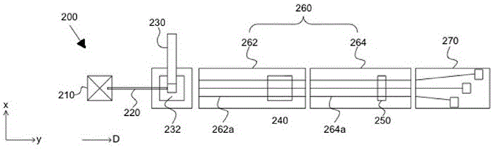
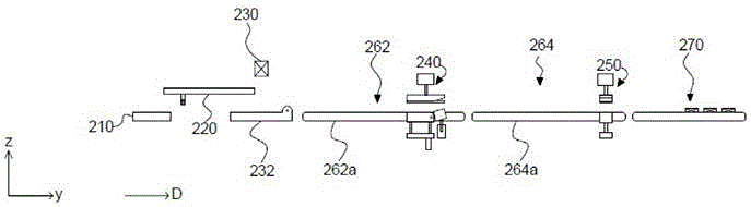
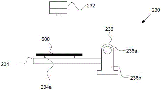
[0030] Please refer to figure 1 - Figure 6C , is a schematic diagram of an automatic cutting and separating equipment for photovoltaic cells according to an embodiment of the present invention. Please ...


PUM


Abstract

The invention provides automatic cutting and separating equipment for phtovoltaic cells. The equipment comprises a feeding device, a laser cutting device, a conveying device, a transverse disconnecting device, a longitudinal disconnecting device and a separating device. After the feeding device conveys stacked cells to the fixed position, laser beams generated by the laser cutting device are used for conducting transverse and longitudinal grooving on the cell surfaces. The cells obtained after grooving are conveyed to the transverse disconnecting device through the conveying device. The transverse oblique-folding part of the transverse disconnecting device is provided with a long shaft, selectively unfolded to form a plane and obliquely folded by an angle. The longitudinal disconnecting device comprises at least two longitudinal oblique-folding parts, a rotating shaft is arranged at the junction of the two adjacent longitudinal oblique-folding parts, the axial direction of the rotating shaft is parallel to the conveying direction, at least one longitudinal oblique-abutting part is selectively unfolded to form a plane and obliquely folded to be an angle by taking the rotating shaft as the axis. The separating device is located on the lower side of the longitudinal disconnecting device, the two adjacent conveying belts form an angle, and cell units are completely separated to different storing locations. The automatic cutting and separating equipment eliminates the phenomenon that a large amount of manual work is adopted in the process in the prior art, full automatic equipment is adopted, the labor cost is greatly lowered, and meanwhile the yield can be increased, and the production efficiency is improved.

Description

technical field [0001] The invention relates to the field of photovoltaic technology, in particular to an automatic cutting and separating device for off-grid photovoltaic cells. Background technique [0002] A photovoltaic cell is a power generation component that converts solar energy into electrical energy without causing environmental pollution. Therefore, in the case of energy shortages, photovoltaic cells have been widely researched and applied. [0003] Common photovoltaic modules include crystalline silicon modules and thin-film modules, among which crystalline silicon modules occupy most of the photovoltaic module market because of their abundant raw materials, mature manufacturing process, and high-efficiency photoelectric conversion advantages. Since a single crystalline silicon cell can only provide an output voltage of 0.5V to 0.7V, several photovoltaic cells are usually connected in series to form a photovoltaic cell module to provide sufficient voltage for use...

Claims


Application Information

Patent Timeline
Patent Type & Authority Applications(China)
IPC IPC(8): H01L31/18H01L21/78
CPCH01L21/78H01L31/1876Y02E10/50Y02P70/50
Inventor 汤鸿祥许泛玮陈彦全
Owner OPES SOLUTIONS (CHANGZHOU) CO LTD FACTORY
Why Eureka
Try Eureka