A processing method of planar waveguide cts array antenna

An array antenna and planar waveguide technology, which is applied in the direction of manufacturing antenna array devices, antennas, antenna arrays, etc., can solve the problems of serious magnetic flux leakage, use restrictions, and magnetic flux leakage.

Active Publication Date: 2019-08-06
NINGBO UNIV
View PDF5 Cites 0 Cited by
  • Summary
  • Abstract
  • Description
  • Claims
  • Application Information

AI Technical Summary

Problems solved by technology

However, it is inevitable that small gaps will appear between the various horizontal layers during assembly. The existence of these gaps will lead to magnetic flux leakage when the signal propagates in the slab waveguide CTS array antenna, and with the increase of frequency, the magnetic flux leakage phenomenon It becomes more serious, it is difficult to be applied to the microwave high frequency band, and the use is limited

Method used


Image

  • A processing method of planar waveguide cts array antenna
  • A processing method of planar waveguide cts array antenna
  • A processing method of planar waveguide cts array antenna

Examples


Embodiment 1

[0030] Embodiment one: a kind of processing method of planar waveguide CTS array antenna, comprises the following steps:

[0031]① Divide the planar waveguide CTS array antenna to be processed into N+1 independent layers according to the following rules, N is the number of series of waveguide "E-T" branches: located above the "E-T" branch of the Nth waveguide and connected to the Nth waveguide " The part where the upper end face of the "E-T" branch intersects is taken as the first independent layer, and the part that is located above the N-1th waveguide "E-T" branch and intersects with the upper end face of the N-1st waveguide "E-T" branch is the second Independent layer, the part located above the "E-T" branch of the N-2 waveguide and intersecting with the upper end face of the N-2 waveguide "E-T" branch is the third independent layer, and so on, located in the first-level waveguide " The part above the "E-T" branch and intersecting the upper end surface of the first-stage wa...

Embodiment 2

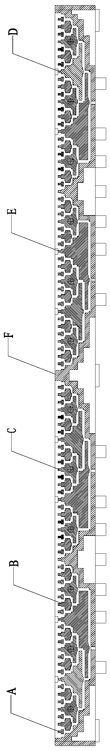
[0038] Embodiment 2: As shown in the figure, a processing method of a slab waveguide CTS array antenna, the number of stages of the "E-T" branch of the slab waveguide CTS array antenna waveguide is 5, including the following steps:

[0039] ① The planar waveguide CTS array antenna to be processed is divided into 6 independent layers according to the following rules: the part located above the "E-T" branch of the fifth-level waveguide and intersecting with the upper end surface of the fifth-level waveguide "E-T" branch is taken as the first The independent layer A is located above the "E-T" branch of the fourth-level waveguide and intersects with the upper end face of the fourth-level waveguide "E-T" branch as the second independent layer B, located above the "E-T" branch of the third-level waveguide and connected to the The intersecting part of the upper end surface of the "E-T" branch of the third-level waveguide is regarded as the third independent layer C, and the part locat...

Embodiment 3

[0044] Embodiment 3: As shown in the figure, a processing method of a slab waveguide CTS array antenna, the number of stages of the "E-T" branch of the slab waveguide CTS array antenna waveguide is 5, including the following steps:

[0045] ① The planar waveguide CTS array antenna to be processed is divided into 6 independent layers according to the following rules: the part located above the "E-T" branch of the fifth-level waveguide and intersecting with the upper end surface of the fifth-level waveguide "E-T" branch is taken as the first The independent layer A is located above the "E-T" branch of the fourth-level waveguide and intersects with the upper end face of the fourth-level waveguide "E-T" branch as the second independent layer B, located above the "E-T" branch of the third-level waveguide and connected to the The intersecting part of the upper end surface of the "E-T" branch of the third-level waveguide is regarded as the third independent layer C, and the part locat...


PUM


Abstract

The invention discloses a processing method of a slab waveguide CTS array antenna. According to the method, the to-be-processed slab waveguide CTS array antenna is divided into N+1 independent layers by taking all stages of waveguide 'E-T' branches as a datum; when processing is conducted, a surrounding edge is arranged at the periphery of the first independent layer to the N-2 independent layer, a surrounding edge is arranged at the periphery of the N+1 independent layer, a clamping groove of which the size matched with that of the surrounding edge of the first independent layer to the N-2 independent layer is formed in the surrounding edge of the N+1 independent layer, and the N-1 independent layer and the N independent layer are installed on the N+1 independent layer through a processing connector; the first independent layer to the N-2 independent layer are sequentially installed; the surrounding edge of the first independent layer to the N-2 independent layer is aligned with the clamping groove formed in the surrounding edge of the N+1 independent layer and clamped into the clamping groove. The processing method has the advantages that the flux leakage phenomenon generated during signal transmission can be reduced, and the method can be applied to processing of the slab waveguide CTS array antenna with the high microwave frequency band.

Description

technical field [0001] The invention relates to a processing method, in particular to a processing method of a planar waveguide CTS array antenna. Background technique [0002] The continuous tangential segment (CTS) antenna was first proposed by Raytheon Corporation of the United States in the 1990s. The CTS array antenna is a continuous transverse slit on the planar waveguide and branches are added to the transverse slit to achieve radiation, using TEM mode feed. Compared with other planar array antennas, the CTS array antenna has the following advantages: the continuous tangential segment antenna has relatively high efficiency, which can reach more than 90%; the continuous tangential segment antenna has a relatively low profile, which can be effectively bonded to the carrier platform; The continuous tangential segment antenna has high feeding efficiency and aperture efficiency, and is an extremely important direction for high-gain antennas. At the same time, the CTS arr...

Claims


Application Information

Patent Timeline
Patent Type & Authority Patents(China)
IPC IPC(8): H01Q21/00
CPCH01Q21/00H01Q21/0087
Inventor 王德乐黄季甫
Owner NINGBO UNIV
Why Eureka
Try Eureka