Charging equipment cooling system

A technology of cooling system and charging equipment, applied in charging stations, electrical equipment structural parts, electric vehicle charging technology, etc., to achieve the effect of ensuring heat dissipation

Pending Publication Date: 2017-06-13
SHENZHEN WOER HEAT SHRINKABLE MATERIAL +2
View PDF0 Cites 32 Cited by
  • Summary
  • Abstract
  • Description
  • Claims
  • Application Information

AI Technical Summary

Problems solved by technology

Circulating fluid piping with built-in coolant

Method used


Image

  • Charging equipment cooling system
  • Charging equipment cooling system
  • Charging equipment cooling system

Examples


Embodiment Construction

[0017] Embodiments of the present invention will be described in detail below. It should be emphasized that the following description is only exemplary and not intended to limit the scope of the invention and its application.

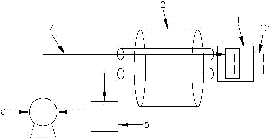
[0018] see figure 1 , The charging device cooling system of the present invention includes a charging gun 1 , a charging cable 2 , a radiator 5 , a circulating pump 6 and a circulating fluid pipeline 7 .

[0019] The circulating fluid pipe 7 contains cooling liquid.

[0020] The charging gun 1, the charging cable 2, and the radiator 5 are connected in series through the circulating fluid pipeline 7 and the heat is taken away through the circulating fluid pipeline. The circulating fluid pipeline 7 transfers the heat to the radiator 5 for heat dissipation. The driving force is provided by the circulating pump 6 .

[0021] As a further improvement of this embodiment, the circulating pump 6, the radiator 5, the charging cable 2 and the charging gun 1 all...


PUM


Abstract

The invention discloses a charging equipment cooling system. The charging equipment cooling system comprises a charging gun, a charging cable, a radiator, a circulating pump and a circulating fluid pipeline. The circulating fluid pipeline is internally provided with cooling liquid. The charging gun and the charging cable are in series connection with each other through the circulating fluid pipeline and heat of the charging gun and the charging cable is taken away through the circulating fluid pipeline, the circulating fluid pipeline transfers the heat to the radiator to conduct heat dissipation, and the driving force of the liquid in the circulating fluid pipeline is provided by the circulating pump. The charging gun is internally provided with a terminal cooling groove, the terminal cooling groove is a liquid cooling groove which is closely attached to terminals in an isolated mode, and the terminal cooling groove is provided with a liquid inlet and a liquid outlet. The liquid in the circulating fluid pipeline flows into the terminal cooling groove through the liquid inlet, and the liquid in the terminal cooling groove is discharged through the liquid outlet and flows into the circulating fluid pipeline. According to the charging equipment cooling system, heat of all parts can be timely dissipated to the outside, and thus timely heat dissipation and the charging safety during big current charging can be guaranteed.

Description

technical field [0001] The invention relates to electric vehicle charging equipment, in particular to a charging equipment cooling system. Background technique [0002] Automobile is a means of transportation with increasing popularity. The operation of automobiles is inseparable from gasoline, and automobile exhaust emissions lead to global warming and environmental degradation, seriously affecting all aspects of the environment. At the same time, gasoline is a non-renewable energy source, and automobile resources are increasingly depleted. Humans have to pay attention to this point. New environmentally friendly and renewable energy will become the main body of the future market, so electric vehicles will be a new territory for future development. Electric vehicles use charging as a power source, and the power consumption is relatively fast. During the charging process, it is necessary to ensure full charging to ensure the driving mileage, so as to prevent the electric veh...

Claims


Application Information

Patent Timeline
Patent Type & Authority Applications(China)
IPC IPC(8): H02J7/00B60L11/18H05K7/20
CPCB60L53/14H02J7/0042H05K7/20272Y02T10/70Y02T10/7072Y02T90/14
Inventor 周诚智周和平康树峰张强邹志平
Owner SHENZHEN WOER HEAT SHRINKABLE MATERIAL
Why Eureka
Try Eureka