Signal amplification system and Hall detection and amplification system

A technology for amplifying systems and oscillating signals, applied in the direction of amplifiers, amplification control, electromagnetic amplifiers, etc., can solve problems such as cumbersome and complicated methods

Active Publication Date: 2017-06-13
CHENGDU MONOLITHIC POWER SYST
View PDF6 Cites 0 Cited by
  • Summary
  • Abstract
  • Description
  • Claims
  • Application Information

AI Technical Summary

Problems solved by technology

Because there is a certain relationship between the gain of the amplifier circuit and the bandwidth of the amplifier circuit, this will cause the gain of the amplifier to change with temperature
The current common practice is to keep the gain constant by trimming, but this method is cumbersome and complicated

Method used


Image

  • Signal amplification system and Hall detection and amplification system
  • Signal amplification system and Hall detection and amplification system
  • Signal amplification system and Hall detection and amplification system

Examples


Embodiment Construction

[0013] Specific embodiments of the present invention will be described in detail below, and it should be noted that the embodiments described here are only for illustration, not for limiting the present invention. In the following description, numerous specific details are set forth in order to provide a thorough understanding of the present invention. It will be apparent, however, to one of ordinary skill in the art that these specific details need not be employed to practice the present invention. In other instances, well-known circuits, materials or methods have not been described in detail in order to avoid obscuring the present invention.

[0014] Throughout this specification, reference to "one embodiment," "an embodiment," "an example," or "example" means that a particular feature, structure, or characteristic described in connection with the embodiment or example is included in the present invention. In at least one embodiment. Thus, appearances of the phrases "in on...


PUM


Abstract

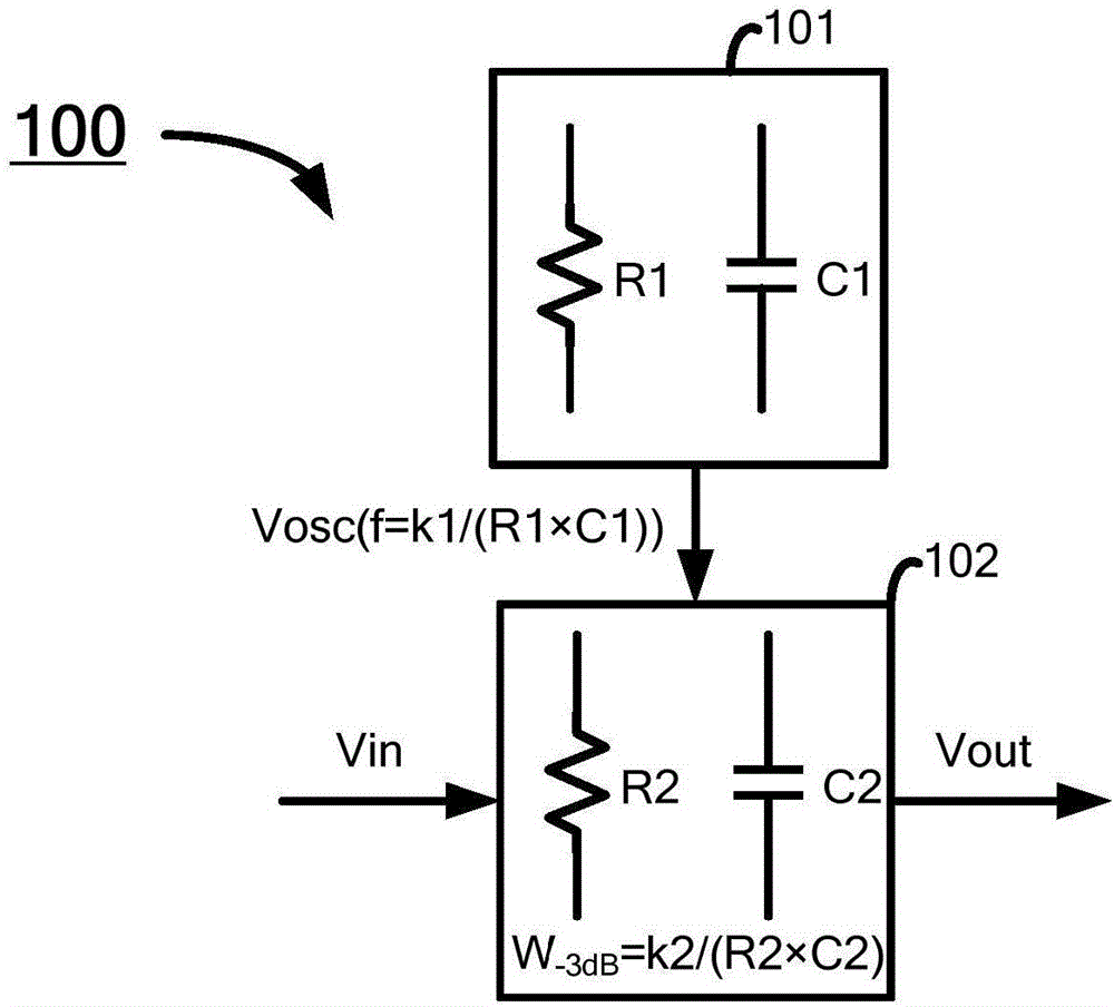
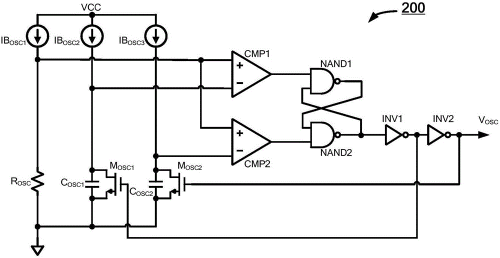
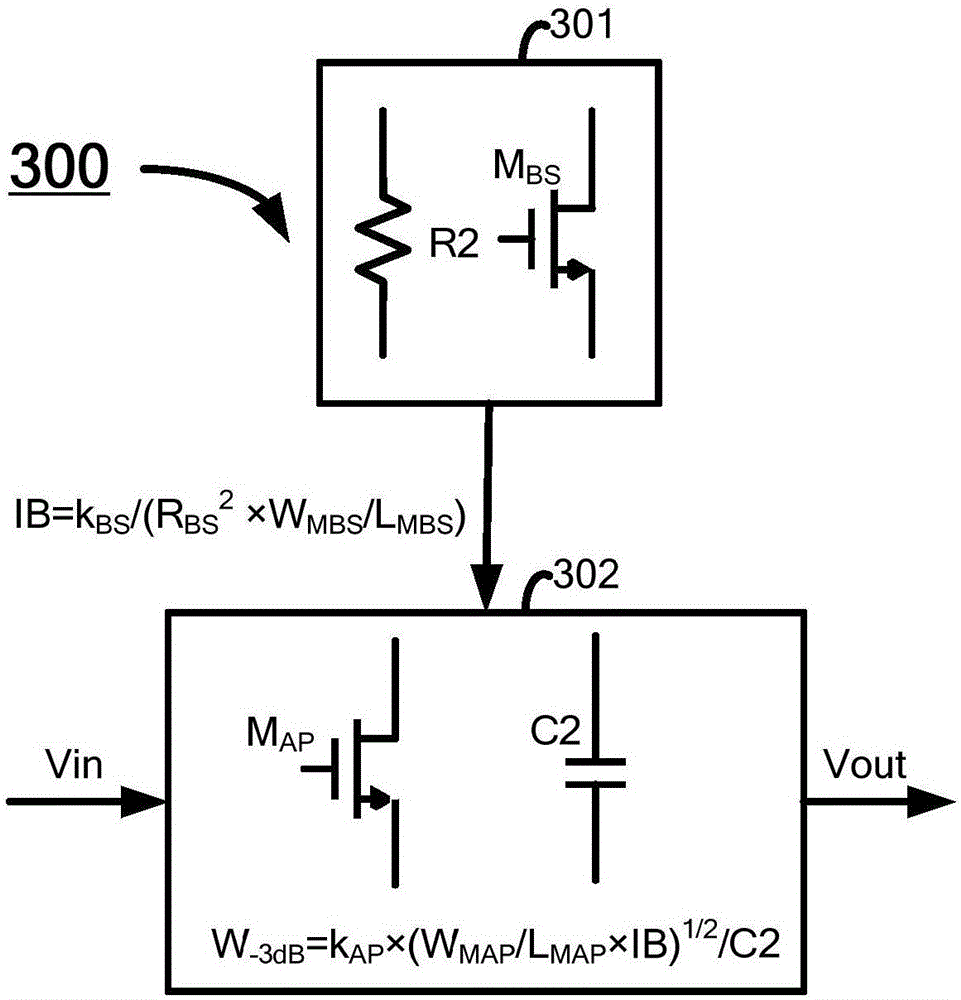
The invention discloses an amplification system. The amplification system comprises an oscillating circuit and an amplification circuit, wherein the oscillating circuit comprises a first resistor with a first resistance value R1 and a first capacitor with a first capacitance value C1; and the oscillating circuit provides an oscillating signal with frequency f, wherein f=k1/(R1*C1), and k1 is a first proportional constant. The amplification circuit is coupled to the oscillating circuit to receive the oscillating signal and amplify an input signal received from the input end of the amplifying circuit under the control of the oscillating circuit; the amplification circuit comprises a second resistor with a second resistance value R2 and a second capacitor with a second capacitance value C2; and the amplification circuit is provided with -3dB bandwidth W-3db, wherein W-3db=k2/(R2*C2), and k2 is a second proportional constant. The ratio of the product of the first resistance value R1 and the first capacitance value C1 to the product of the second resistance value R2 and the second capacitance value 2 is a constant. The amplification system disclosed by the embodiment of the invention has constant gain.

Description

technical field [0001] The present invention relates to electronic circuits, and more particularly, the present invention relates to amplifying circuits. Background technique [0002] In some Hall voltage amplifying circuit applications, the gain of the amplifying circuit is required to be constant over the entire temperature range. For example, when Hall sensors are used for current detection, since white noise exists in the entire bandwidth, in order to reduce the influence of white noise, the bandwidth of the amplifier circuit is required to be narrow. Because there is a certain relationship between the gain of the amplifier circuit and the bandwidth of the amplifier circuit, this will cause the gain of the amplifier to vary with temperature. The current common practice is to keep the gain constant by trimming, but this method is cumbersome and complicated. [0003] Therefore, it is necessary to propose an amplifying circuit whose gain is constant in the whole temperatu...

Claims


Application Information

Patent Timeline
Patent Type & Authority Applications(China)
IPC IPC(8): H03F1/30H03G3/30
CPCH03F1/301H03G3/30H03F3/345H03F3/45183H03F2200/261G01R33/0023G01R33/072H03F15/00H03F9/04G01R33/00
Inventor 杨志江
Owner CHENGDU MONOLITHIC POWER SYST
Why Eureka
Try Eureka