
Resource task scheduling method for optical matrix network

A task scheduling, optical matrix technology, applied in the direction of network interconnection, data switching network, multiplexing system selection device, etc., can solve the problems of high time complexity, unsuitable for resource scheduling, etc. The effect of fast automatic scheduling and workload reduction

Inactive Publication Date: 2017-06-13
NAT COMP NETWORK & INFORMATION SECURITY MANAGEMENT CENT
View PDF6 Cites 0 Cited by
  • Summary
  • Abstract
  • Description
  • Claims
  • Application Information

AI Technical Summary

Problems solved by technology

[0007] Both of the above two methods have high time complexity and are not suitable for resource scheduling in existing cloud computing

Method used


Image

  • Resource task scheduling method for optical matrix network
  • Resource task scheduling method for optical matrix network
  • Resource task scheduling method for optical matrix network

Examples


Embodiment Construction

[0042] The present invention will be further described in detail below in conjunction with the accompanying drawings and embodiments.

[0043] Optical matrix network:

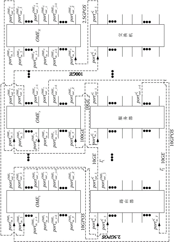
[0044] see figure 2 As shown, in the present invention, a plurality of optical matrix equipment (Optical Matrix Equipment) constitutes an optical matrix network (Optical Matrix Network). The optical matrix network is denoted as OMN, the optical matrix equipment is denoted as OME, and X optical matrix equipment OME constitutes an optical matrix network OMN. Any optical matrix equipment is marked as OME x , x represents the identification number of the optical matrix device, x∈X. The optical matrix network is expressed in the form of a set, that is, OMN={OME 1 ,OME 2 ,...,OME x-1 ,OME x ,OME x+1 ,...,OME X}.

[0045] OME 1 Indicates the first optical matrix device in the optical matrix network.

[0046] OME 2 Indicates the second optical matrix device in the optical matrix network.

[0047] OME x ...


PUM


Abstract

The invention discloses a resource task scheduling method for an optical matrix network. The method comprises the following steps: networking a network device in a cloud computing system and an optical matrix device; generating a virtual request network according to user demands; mapping the virtual request network into the optical matrix network to accomplish the resource task scheduling represented by the virtual request network so as to obtain a physical subnet having the same logic structure as the virtual request network, and finally feeding back the physical subnet to the user, wherein the resource task scheduling comprises two stages of device mapping and link mapping, virtual devices not occupying excessive ports are preferentially mapped by using a greedy strategy, and the links between the virtual devices are quickly matched depending on the attribute advantages of the optical matrix so as to find the physical subnet satisfying the user demands. By adoption of the method disclosed by the invention, automatic resource scheduling can be realized more quickly, moreover the accuracy is guaranteed, and a matchable physical device in the same optical matrix is preferentially selected with the utilization rate of the ports of the optical matrix as the starting point.

Description

technical field [0001] The present invention relates to a task scheduling of a cloud computing system, more particularly, a resource task scheduling method oriented to an optical matrix network. Background technique [0002] Cloud computing (Clond Computing) is grid computing (Grid Computing), distributed computing (Distributed Computing), parallel computing (Parallel Computing), utility computing (Utility Computing), network storage (Network Storage Technologies), virtualization (Virtualization), load It is the product of the integration of traditional computer technology and network technology such as Load Balance. It aims to integrate multiple relatively low-cost computing entities into a perfect system with powerful computing capabilities through the network, and distribute this powerful computing capabilities to end users with the help of advanced business models such as SaaS, PaaS, IaaS, and MSP hands. One of the core concepts of Clond Computing is to reduce the proc...

Claims


Application Information

Patent Timeline
IPC IPC(8): H04Q11/00H04L12/46H04L12/931H04L29/08
CPCH04Q11/0062H04L12/4641H04L49/70H04L67/10H04Q11/0005H04Q2011/0058H04Q2011/0086
Inventor 李焱余舒敏唐积强邹潇湘王维晟何清林
Owner NAT COMP NETWORK & INFORMATION SECURITY MANAGEMENT CENT
Features
  • Generate Ideas
  • Intellectual Property
  • Life Sciences
  • Materials
  • Tech Scout
  • Unparalleled Data Quality
  • Higher Quality Content
  • 60% Fewer Hallucinations
Learn More