Serial connection type power dividing ball joint

A tandem and ball technology, which is applied in the direction of manufacturing tools, manipulators, belts/chains/gears, etc., can solve the problems of poor repeat positioning accuracy, high price, and large volume of RV reducers

Active Publication Date: 2017-06-16
池州市弥优机床有限公司
View PDF3 Cites 3 Cited by
  • Summary
  • Abstract
  • Description
  • Claims
  • Application Information

AI Technical Summary

Problems solved by technology

[0003] The technical problem to be solved by the present invention is to provide a tandem power split ball joint

Method used


Image

  • Serial connection type power dividing ball joint
  • Serial connection type power dividing ball joint
  • Serial connection type power dividing ball joint

Examples


Embodiment Construction

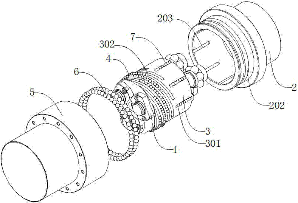
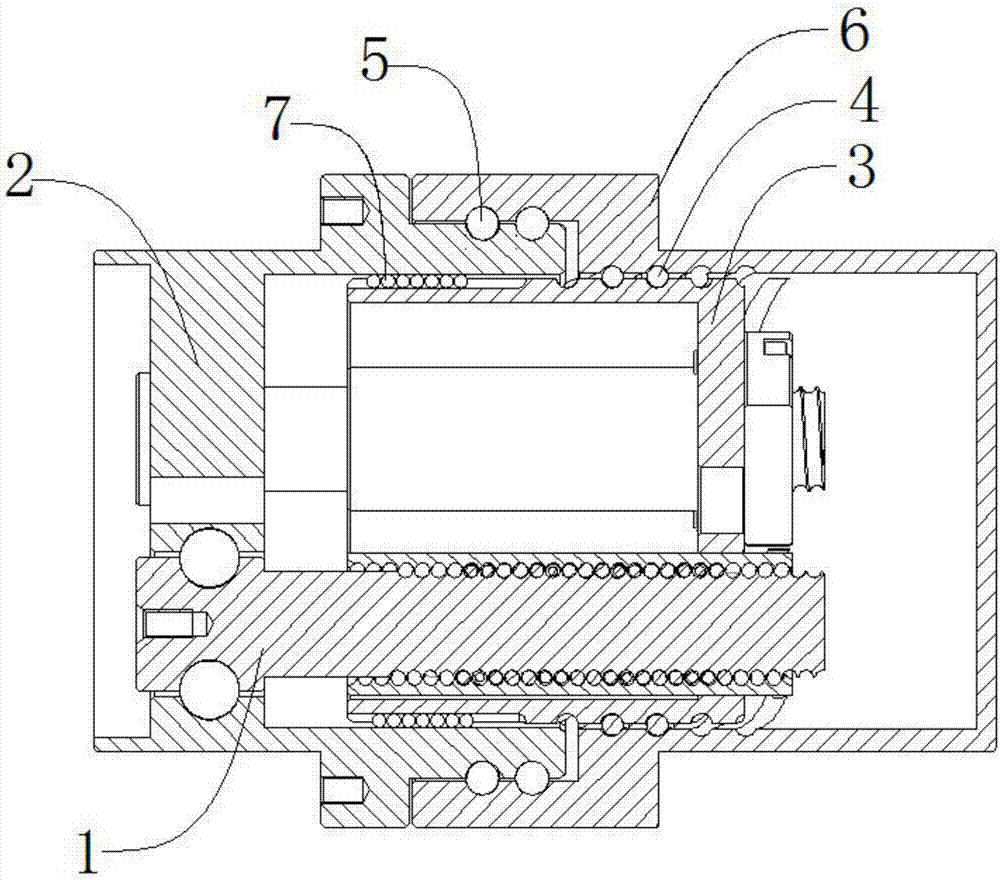
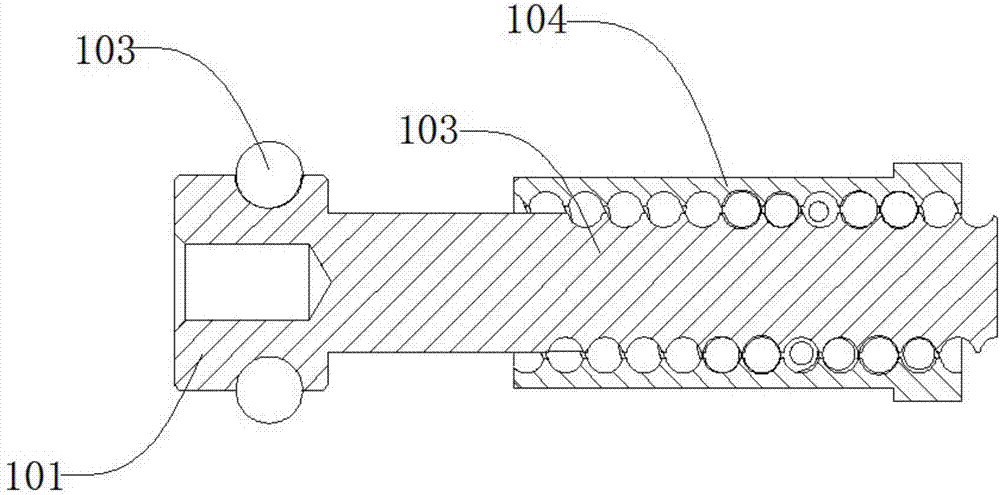
[0033] Such as figure 1 , figure 2 , image 3 , Figure 4 , Figure 5 , Figure 6As shown, a tandem power splitting ball joint includes not less than two pieces of high-speed screw mechanism 1, static ring 2, low-speed nut sleeve 3, low-speed ball 4, moving coil 5, first supporting ball 6, guide Ball 7, the static ring 2 is located outside the high-speed screw mechanism 1, the static ring 2 is rollingly connected with the high-speed screw mechanism 1, and the low-speed nut sleeve 3 is penetrated by the high-speed screw mechanism 1 and located on the static ring 2, the low-speed nut sleeve 3 is threadedly connected with the high-speed screw mechanism 1 and is movably connected with the static ring 2, the low-speed ball 4 is located outside the low-speed nut sleeve 3, and the low-speed ball 4 is connected to the low-speed nut sleeve 3 rolling connection, the moving ring 5 is located outside the low-speed ball 4 and outside the static ring 2, the moving ring 5 is rollingly ...


PUM


Abstract

The invention discloses a serial connection type power dividing ball joint which comprises more than two high-speed screw mechanisms, a static ring, a low-speed nut sleeve, low-speed balls, a dynamic ring, first support balls and guide balls, multiple groups of high-speed screw mechanisms work, feed nuts and the low-speed nut sleeve can only move along high-speed screws due to fixed connection, at the same time, the low-speed nut sleeve, the low-speed balls and the dynamic ring form a screw transmission pair, and the guide balls limit the low-speed nut sleeve to rotate, so that the low-speed nut sleeve converts linear movement into rotation of the dynamic ring, and accordingly, gearing-down transmission is realized. The device structure is simple, power dividing is performed through the multiple groups of high-speed screw mechanisms, not only are the transmission accuracy and bearing capacity high, but also the manufacturing cost is low, and the transmission efficiency is high; at the same time, the structure is compact, the size is small, the movement is almost pure rolling movement, the friction coefficient is very low, the hysteresis phenomenon in the transmission is reduced, and the repeated positioning accuracy of the robot joint is improved from the source.

Description

technical field [0001] The invention relates to a mechanical device, in particular to a series power split ball joint. Background technique [0002] Existing robot joints mainly include power mechanisms (such as motors), transmission mechanisms (such as gears), and reducers. Most of the existing reducers for robot joints are RV reducers. Gear housings, planetary carriers, and eccentric shafts are all thin-walled and special-shaped parts. It is difficult to achieve micron-level machining accuracy under domestic production conditions, and it is difficult to carry out mass production. There are strict phase requirements during assembly, and the adjustment process is complicated. As a result, the RV reducer is expensive. At the same time, in order to ensure that there is no motion dead zone, the traditional RV reducer must reserve a small meshing gap, resulting in a space backlash that can only be controlled within 1 arc minute, which not only reduces the positioning accuracy, b...

Claims


Application Information

Patent Timeline
IPC IPC(8): F16H25/22B25J17/02
CPCF16H25/2204B25J17/02
Inventor 胡建东陈贤湘陈平赵永芹
Owner 池州市弥优机床有限公司
Why Eureka
Try Eureka