
Vision sensing based AFM (Automatic Force Microscope) system mechanical drift compensation method

A technology of visual sensing and mechanical drift, applied in the field of precision measurement, can solve the problems of high cost, limited popularization and application, and lack of real-time performance, and achieve the effect of solving the drift problem

Active Publication Date: 2017-06-16
BEIHANG UNIV
View PDF4 Cites 5 Cited by
  • Summary
  • Abstract
  • Description
  • Claims
  • Application Information

AI Technical Summary

Problems solved by technology

The above compensation schemes for AFM system drift have improved the system drift. The hardware modification method is costly and limited by the AFM system structure, and the software algorithm offline correction method is not real-time, which limits its popularization and application.

Method used


Image

  • Vision sensing based AFM (Automatic Force Microscope) system mechanical drift compensation method
  • Vision sensing based AFM (Automatic Force Microscope) system mechanical drift compensation method
  • Vision sensing based AFM (Automatic Force Microscope) system mechanical drift compensation method

Examples


Embodiment Construction

[0026] In order to make the object, technical solution and advantages of the present invention clearer, the present invention will be further described in detail below in conjunction with the accompanying drawings and embodiments. The specific embodiments described here are only used to explain the present invention, not to limit the present invention.

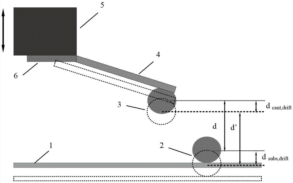
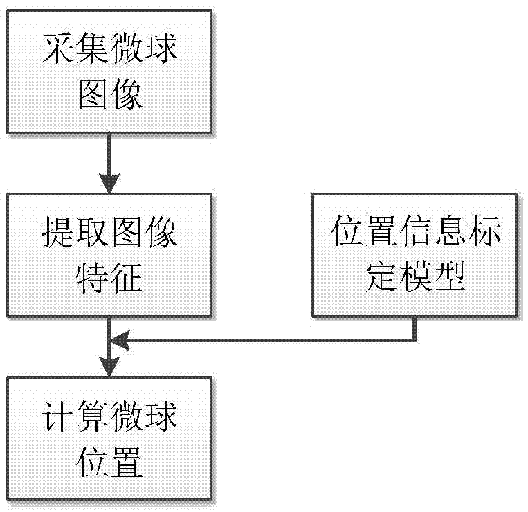
[0027] The method of the invention adopts the visual sensing technology to measure and compensate the drift of the AFM system in real time in a non-contact manner without modifying the hardware of the AFM system. The mechanical drift compensation method of the AFM system based on visual sensing is characterized in that the visual sensing part includes a microsphere at the end of the AFM cantilever and a microsphere on the surface of the sample, and the microsphere is a microsphere with a diameter of 10 μm-50 μm. Sensing technology measures the distance between the microspheres at the end of the AFM cantilever and the microsphe...


PUM


Abstract

The invention belongs to the field of precision measurement, and relates to a vision sensing based AFM (Automatic Force Microscope) system mechanical drift compensation method. The method is characterized in that an AFM system drift compensation algorithm is built on the basis of positioning the position of microspheres under a microscope through image processing. Due to influences imposed on an AFM system by factors such as mechanical vibration and noise interference, the variation in distance between a cantilever tail end microsphere and a sample surface microsphere is accumulation of the drift of the AFM system, and driver voltage of a platform at which the microspheres are located is adjusted according to the measured distance variation, so that the distance between the cantilever tail end microsphere and the sample surface microsphere is enabled to be kept as a constant, and thus compensation for the drift amount of the AFM system is realized. Compared with an existing AFM system drift compensation method, the method provided by the invention has the advantages of ability of not changing hardware of the AFM system and non-contact measurement, and can compensate the drift of the AFM system in real time.

Description

technical field [0001] The invention belongs to the field of precision measurement, and in particular relates to a method for compensating mechanical drift of an AFM system based on vision sensing. Background technique [0002] AFM (Atomic Force Microscope, Atomic Force Microscope) conducts morphology detection and micro-nano manufacturing and processing by detecting the force between the probe and the surface atoms of the sample. It is now widely used in the research fields of semiconductors, nano-functional materials, biology, and chemical engineering. middle. During the long-term working process of AFM, environmental temperature changes, mechanical vibration, electromagnetic interference and other factors lead to serious drift of the system, causing distortion of the image of the object to be measured and position measurement errors. [0003] At present, the research direction of AFM system drift can be divided into two categories: one is to suppress drift in hardware de...

Claims


Application Information

Patent Timeline
Patent Type & Authority Applications(China)
IPC IPC(8): G01B11/00G01B11/02G01Q60/24
CPCG01B11/00G01B11/02G01Q60/24
Inventor 王玉亮李晓来
Owner BEIHANG UNIV
Learn More