Array substrate, display panel and display device

A technology for array substrates and base substrates, applied in the field of display panels, display devices, and array substrates, can solve problems such as crosstalk and adverse effects on display effects, and achieve the effects of reducing parasitic capacitance, improving display effects, and reducing crosstalk

Active Publication Date: 2017-06-16
XIAMEN TIANMA MICRO ELECTRONICS
5 Cites 18 Cited by

AI-Extracted Technical Summary

Problems solved by technology

[0006] As the resolution of the display device becomes higher and higher, the size of the sub-pixel area becomes smaller and smaller, and the distance between the data line and the drain electrode becomes smaller and smaller, so a parasitic capacitance is for...

Method used

[0038] When the array substrate is in operation, an electric field will be generated between the drain electrode 42 and its adjacent data line 3, forming a parasitic capacitance. In the embodiment of the present invention, the position between the drain electrode 42 and the data line 3 The barrier metal 6 is provided, so that part of the electric field generated between the source electrode 42 and the data line 3 will be shielded by the barrier metal 6 , thereby reducing the parasitic capacitance between the source electrode 42 and the data line 3 . In each sub-pixel region, the shape, position and quantity of the barrier metal 6 can be determined as required. For example, as shown in FIG. 4, FIG. The electrode 42 is arranged at a position close to the left in the sub-pixel area, that is, the distance between the drain electrode 42 and the data line 3 on the left is relatively short, and the distance between the drain electrode 42 and the data line 3 on the right is relatively long, so The parasitic capacitance formed between the drain 42 and the data line 3 on the left is relatively large, while the parasitic capacitance formed between the drain 42 and the data line 3 on the right is relatively small. In this structure, only the drain 42 and Barrier metal 6 is provided between adjacent data lines 3 on the left to reduce the parasitic capacitance formed between the drain 42 and the data line 3 on the left.
[0039] In the array substrate in the embodiment of the present invention, a barrier metal is provided at a position between the drain electrode and its adjacent data line, and the shielding effect of the barrier metal on the electric field reduces the distance between the drain electrode and the data line. Parasitic capacitance, thereby reducing the resulting crosstalk and improving the display effect.
[0040] Optionally, in the array substrate shown in FIG. 2 and FIG. 3, in each sub-pixel region, the barrier metal 6 includes a first barrier metal 61 and a second barrier metal 62; two adjacent data lines 3 Respectively, the first data line 31 and the second data line 32; between the first data line 31 and the second data line 32, the orthographic projection of the first barrier metal 61 on the base substrate is located at the drain 42 on the base substrate between the orthographic projection of the first data line 31 on the base substrate, the orthographic projection of the second barrier metal 62 on the base substrate is located between the orthographic projection of the drain 42 on the base substrate and the second data line Line 32 is between the orthographic projections on the substrate substrate. In some polarity inversion driving methods, such as column inversion, when displaying, the voltage polarities on the data lines of two adjacent columns are opposite. Therefore, as shown in FIG. 2 and FIG. The method of setting the first barrier metal 61 and the second barrier metal 62 on both sides can further reduce the parasitic capacitance formed on the left and right sides of the drain 42 while ensuring that the parasitic capacitances formed on the left and right sides of the drain 42 cancel each other out to a certain extent. parasitic capacitance.
[0042] Optionally, as shown in FIG. 2, between the first data line 31 and the second data line 32, the distance L1 between the drain 42 and the first data line 31 is equal to the distance L1 between the drain 42 and the second data line. The distance L2 between the lines 32 , the distance M1 between the drain 42 and the first barrier metal 61 is equal to the distance M2 between the drain 42 and the second barrier metal 62 . When the distance L1 between the drain electrode 42 and the first data line 31 is equal to the distance L2 between the second data line 32, the parasitic capacitance formed by the drai...

Abstract

The embodiment of the invention discloses an array substrate, a display panel and a display device and relates to the technical field of display. A display effect can be improved. The array substrate comprises a substrate base plate, multiple scan lines and multiple data lines, multiple subpixel zones defined by the multiple scan lines and the multiple data lines in an insulated and crossed mode, and thin film transistors, pixel electrodes and barrier metals correspondingly arranged in the subpixel zones. The orthographic projections of drain electrodes on the substrate base plate are located among the orthographic projections of every two adjacent data lines on the substrate base plate, and orthographic projections of the barrier metals on the substrate base plate are located among the orthographic projections of the drain electrodes on the substrate base plate and the orthographic projection of at least one of every two adjacent data lines on the substrate base plate. The scheme is mainly used for the liquid-crystal display device, the stray capacitance between the data lines and pixel electrodes is reduced, accordingly crosstalk caused by the stray capacitance is decreased, and a display effect is improved.

Application Domain

Technology Topic

Image

  • Array substrate, display panel and display device
  • Array substrate, display panel and display device
  • Array substrate, display panel and display device

Examples

  • Experimental program(1)

Example Embodiment

[0034] In order to better understand the technical solutions of the present invention, the embodiments of the present invention are described in detail below with reference to the accompanying drawings.
[0035] It should be understood that the described embodiments are only some, but not all, embodiments of the present invention. Based on the embodiments of the present invention, all other embodiments obtained by those of ordinary skill in the art without creative efforts shall fall within the protection scope of the present invention.
[0036] The terms used in the embodiments of the present invention are only for the purpose of describing specific embodiments, and are not intended to limit the present invention. As used in the embodiments of the present invention and the appended claims, the singular forms "a," "the," and "the" are intended to include the plural forms as well, unless the context clearly dictates otherwise.
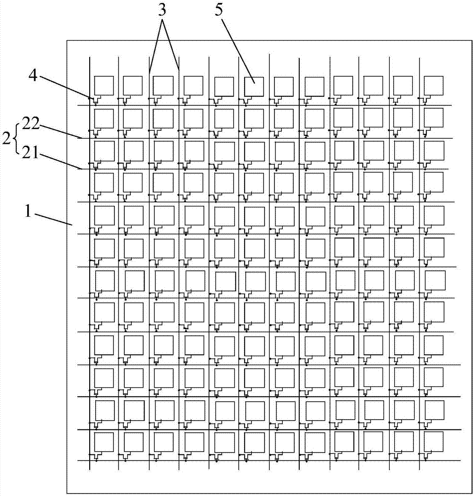
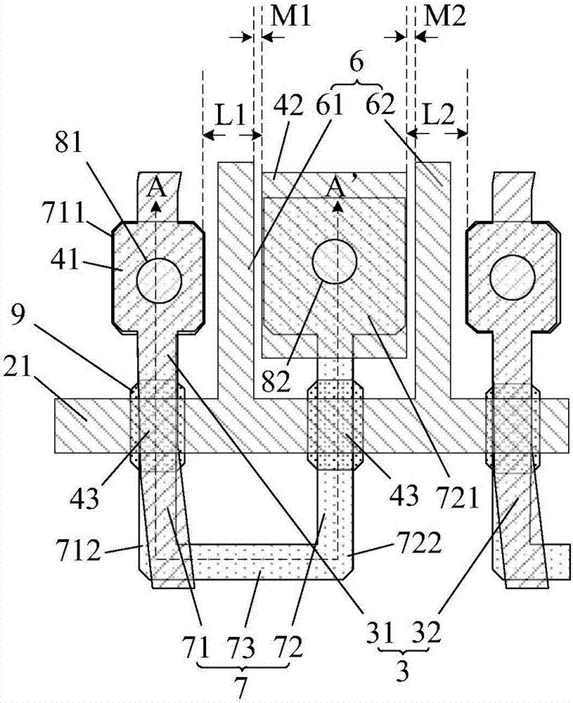
[0037] like figure 1 , figure 2 and image 3 shown, figure 1 It is a schematic structural diagram of an array substrate in an embodiment of the present invention, figure 2 for figure 1 A partially enlarged schematic diagram of a part of the area in the array substrate, image 3 for figure 2 The cross-sectional structure diagram of the middle AA' direction, an embodiment of the present invention provides an array substrate, including: a base substrate 1; a plurality of gate lines 2 and a plurality of data lines 3 located on the base substrate 1; a plurality of gate lines 2 and a plurality of data lines 3 are insulated and crossed to define a plurality of sub-pixel regions; the thin film transistor 4, the pixel electrode 5 and the barrier metal 6 are arranged corresponding to each sub-pixel region, and the thin film transistor 4 includes a source electrode 41, a drain electrode 42 and a gate electrode 43 and the active layer 7, the source electrode 41 is connected to the data line 3, and the figure 2 , the source electrode 41 is a part of the data line 3, such as image 3 As shown, the source electrode 41 and the drain electrode 42 are located in the source-drain metal layer, an insulating layer 8 is arranged between the source-drain metal layer and the active layer 7, and a source via hole 81 and a drain via hole are arranged on the active layer 8 82, as figure 2 As shown, the source 41 is connected to the active layer 7 through the source via 81, the drain 42 is connected to the active layer 7 through the drain via 81, and the drain 42 is connected to the pixel electrode 5 ( figure 2 The pixel electrode 5) is not shown, the gate 43 is connected to the gate line 2, and the figure 2 Among them, the gate 43 is a part of the gate line 2, and the overlapping part of the gate line 2 and the active layer 7 is the gate 43; the orthographic projection of the drain 42 on the substrate is located in the adjacent two data lines 3 Between the orthographic projections on the base substrate, the orthographic projection of the barrier metal 6 on the base substrate is located between the orthographic projection of the drain 42 on the base substrate and at least one data line 3 of the two adjacent data lines 3 Between orthographic projections on the base substrate. The array substrate also includes a light shielding layer 9 located between the active layer 7 and the base substrate 1 for shielding the channel region of the active layer 7, and the channel region is the orthographic projection of the gate line 2 on the active layer 7 and the The overlapping area of ​​the active layer 7 . The gate line 43 is used to transmit the control signal of the thin film transistor 4, and the data line 3 is used to transmit the pixel voltage signal required by the pixel electrode 5. When the array substrate is working, under the control of the corresponding gate line 43, the data line corresponding to the source electrode 41 3. The pixel electrode 5 corresponding to the drain electrode 42 is charged and discharged through the thin film transistor 4, and an electric field is formed between the pixel electrode 5 and the common electrode 6, so as to realize the display function.
[0038] When the array substrate is in operation, an electric field will be generated between the drain 42 and its adjacent data line 3 to form a parasitic capacitance, and in the embodiment of the present invention, a barrier metal is provided at the position between the drain 42 and the data line 3 6. In this way, the electric field generated between the source electrode 42 and the data line 3 is partially shielded by the blocking metal 6, thereby reducing the parasitic capacitance between the source electrode 42 and the data line 3. In each sub-pixel area, the shape, position and quantity of the blocking metal 6 can be determined as required, for example, as Figure 4 shown, Figure 4 for figure 1 Another partially enlarged schematic diagram of a part of the array substrate in the . The distance between the drain 42 and the data line 3 on the right is far, so the parasitic capacitance formed between the drain 42 and the data line 3 on the left is larger, and the parasitic capacitance formed between the drain 42 and the data line 3 on the right is larger. The parasitic capacitance is small. In this structure, only the blocking metal 6 can be arranged between the drain 42 and the data line 3 on the left side thereof, so as to reduce the parasitic capacitance formed between the drain 42 and the data line 3 on the left side. .
[0039] In the array substrate in the embodiment of the present invention, a barrier metal is provided at the position between the drain and the adjacent data line, and the parasitic capacitance between the drain and the data line is reduced by the shielding effect of the barrier metal on the electric field. Thus, the resulting crosstalk is reduced, and the display effect is improved.
[0040] Optionally, in figure 2 and image 3 In the array substrate shown, in each sub-pixel area, the barrier metal 6 includes a first barrier metal 61 and a second barrier metal 62; the adjacent two data lines 3 are the first data line 31 and the second data line 32 respectively. ; Between the first data line 31 and the second data line 32, the orthographic projection of the first barrier metal 61 on the base substrate is located in the orthographic projection of the drain 42 on the base substrate and the orthographic projection of the first data line 31 on the substrate Between the orthographic projections on the substrate, the orthographic projection of the second barrier metal 62 on the base substrate is located between the orthographic projection of the drain 42 on the base substrate and the orthographic projection of the second data line 32 on the base substrate. In some polarity inversion driving modes, such as column inversion, during display, the voltage polarities on the data lines of two adjacent columns are opposite. Therefore, figure 2 and image 3The method of disposing the first blocking metal 61 and the second blocking metal 62 on the left and right sides of the drain 42 as shown in can ensure that the parasitic capacitances formed on the left and right sides of the drain 42 cancel each other to a certain extent, and further The parasitic capacitance formed on the left and right sides of the drain 42 is reduced.
[0041] Optionally, as figure 2 As shown, the shape and size of the first blocking metal 61 and the second blocking metal 62 are the same to ensure that the first blocking metal 61 and the second blocking metal 62 have the same reduction effect on the parasitic capacitance formed on the left and right sides of the drain 42 .
[0042] Optionally, as figure 2 As shown, between the first data line 31 and the second data line 32, the distance L1 between the drain 42 and the first data line 31 is equal to the distance L2 between the drain 42 and the second data line 32, and the drain The distance M1 between the drain 42 and the first blocking metal 61 is equal to the distance M2 between the drain 42 and the second blocking metal 62 . When the distance L1 between the drain 42 and the first data line 31 is equal to the distance L2 between the second data lines 32, the parasitic capacitances formed on the left and right sides of the drain 42 are approximately equal, so the drain 42 and the first barrier are provided The distance M1 between the metals 61 is equal to the distance M2 between the drain 42 and the second barrier metal 62 , which further ensures the reduction effect of the first barrier metal 61 and the second barrier metal 62 on the parasitic capacitance formed on the left and right sides of the drain 42 . equal.
[0043] Specifically, in an optional implementation, as figure 1 , figure 2 and 3 As shown, in the above-mentioned array substrate, the active layer 7 includes a first segment 71, a second segment 72 and a third segment 73; the orthographic projection of the drain electrode 42 on the base substrate is located on the adjacent two gate lines 2 on the backing Between the orthographic projections on the bottom substrate; the adjacent two grid lines 2 are the first grid line 21 and the second grid line 22 ( figure 2 Only the first gate line 21 is shown in the figure); the drain 42 is located on the side close to the first gate line 21 in the sub-pixel region; 72 includes a first end 721 and a second end 722 arranged oppositely, and the orthographic projection of the first end 711 of the first segment 71 and the first end 721 of the second segment 72 on the substrate is located on the substrate of the first gate line 21. The orthographic projection on the base substrate is close to the side of the orthographic projection of the drain 42 on the base substrate, and the second end 712 of the first segment 71 and the second end 722 of the second segment 72 and the third segment 73 are on the base substrate. The orthographic projection of the first gate line 21 on the base substrate is located on the side away from the orthographic projection of the drain 42 on the base substrate; the third segment 73 is connected to the second end 712 of the first segment 71 and The second end 722 of the second segment 72; the first end 711 of the first segment 71 is connected to the source electrode 41 through the source via 81, and the first end 721 of the second segment 72 is connected to the drain through the drain via 82 42. In this structure, the active layer 7 is a U-shaped structure, and the thin film transistor is a double-gate structure. The embodiment of the present invention does not limit the specific structure of the thin film transistor. For example, in some other feasible implementations, the thin film transistor may also be a single-gate structure. gate structure.
[0044] Specifically, as Figure 5 and Image 6 shown, Figure 5 for figure 1 Another partially enlarged schematic diagram of part of the area in the array substrate, Image 6 for Figure 5 A schematic diagram of the cross-sectional structure in the direction of BB', the source electrode 41 and the drain electrode 42 are located in the source-drain metal layer, an insulating layer 8 is arranged between the source-drain metal layer and the active layer 7, and a source via hole 81 is arranged on the insulating layer 8 and the drain via 82, the source 41 is connected to the first end 711 of the first segment 71 through the source via 81, the drain 42 is connected to the first end 721 of the second segment 72 through the drain via 82; the source The distance between the orthographic projection of the pole via 81 on the base substrate and the orthographic projection of the first gate line 21 on the base substrate is h1, and the orthographic projection of the drain via 82 on the base substrate is far from the first gate The distance between one end of the orthographic projection of the line 21 on the base substrate and the orthographic projection of the first grid line 21 on the base substrate is h2, and h1>h2. When the distance between the source electrode 41 and the drain electrode 42 is relatively close, the crosstalk caused by the parasitic capacitance formed between the data line 3 and the drain electrode 42 is more serious, for example figure 2 The source electrode 41 and the drain electrode 42 in the Figure 5 In the shown structure, the distance between the source electrode 41 and the drain electrode 42 is relatively far, thereby reducing the crosstalk caused by the parasitic capacitance.
[0045] Optionally, as Figure 5 As shown, the distance between the end of the orthographic projection of the first barrier metal 61 on the base substrate that is far from the orthographic projection of the first grid line 21 on the base substrate and the orthographic projection of the first grid line 21 on the base substrate is h3, the distance between the end of the orthographic projection of the second barrier metal 62 on the base substrate that is far from the orthographic projection of the first grid line 21 on the base substrate and the orthographic projection of the first grid line 21 on the base substrate For h4, h3>h2, h4>h2, the barrier metal 6 is located between the drain 42 and the data line 3 to ensure that the barrier metal 6 reduces the parasitic capacitance formed between the drain 42 and the data line 3.
[0046] Further, as Figure 5 As shown, h1>h3, and h1>h4, the top of the source via 82 is higher than the top of the blocking metal 6, that is, when the distance between the source 41 and the drain 42 is long, there will be no difference between the two. To generate parasitic capacitance, the barrier metal 6 does not need to be located between the source electrode 41 and the drain electrode 42, but only needs to be arranged between the data line 3 and the drain electrode 42. Therefore, the barrier metal 6 can be arranged outside the opening area of ​​the pixel. It will not adversely affect the transmittance of the array substrate.
[0047] Optionally, as figure 2 and Figure 7 shown, Figure 7 for figure 1 Another partially enlarged schematic diagram of a part of the array substrate in the 2nd array substrate, the first barrier metal 61 and the second barrier metal 62 are both lateral extension parts of the first gate line 21, that is, the barrier metal 6 is formed when the gate line 2 is formed. , thereby simplifying the fabrication process of the barrier metal 6 .
[0048] except as figure 2 and Figure 7 In addition to the manner in which the barrier metal 6 is formed by the gate line 2, the barrier metal may also be formed in other manners, for example, as shown in FIG. Figure 5 and Image 6 As shown, the above-mentioned array substrate further includes: a light shielding layer 9 located between the active layer 7 and the base substrate 1; the orthographic projection of the first gate line 21 on the base substrate and the projection of the first segment 71 on the base substrate The orthographic projection has a first overlapping area, and the orthographic projection of the first grid line 21 on the base substrate and the orthographic projection of the second segment 72 on the base substrate have a second overlapping area; the light shielding layer 9 includes a first light shielding portion 91 and the second shading portion 92, the orthographic projection of the first shading portion 91 on the base substrate covers the first overlapping area, the orthographic projection of the second shading portion 92 on the base substrate covers the second overlapping area, the first The barrier metal 61 is an extension of the first light shielding portion 91 , and the second barrier metal 62 is an extension of the second light shielding portion 92 . The light shielding layer 9 is used to shield the channel region to prevent the adverse effect of light on the leakage current in the thin film transistor, and the blocking metal 6 is formed when the light shielding layer 9 is formed, thereby simplifying the manufacturing process of the blocking metal 6 .
[0049] Optionally, in addition to the above-mentioned U-shaped active layer structure, the active layer may also have other shapes, such as Figure 8 The L-type active layer structure shown in 1 and Figure 8 shown, Figure 8 for figure 1 Another partially enlarged schematic diagram of a partial area in the array substrate, the array substrate further includes: an active layer 7, the active layer 7 includes a first segment 71 and a second segment 72; the orthographic projection of the drain electrode 42 on the base substrate Located between the orthographic projections of the adjacent two grid lines 2 on the base substrate; the adjacent two grid lines 2 are the first grid line 21 and the second grid line 22 ( Figure 8 Only the first gate line 21 is shown); the drain 42 is located on the side of the sub-pixel region close to the first gate line 21; 72 includes a first end 721 and a second end 722 arranged oppositely, and the orthographic projections of the first end 711 and the second segment 72 of the first segment 71 on the base substrate are located at the positive side of the first gate line 21 on the base substrate. The projection is close to the side of the orthographic projection of the drain 42 on the base substrate, and the orthographic projection of the second end 712 of the first segment 71 on the base substrate is located at the orthographic projection of the first gate line 21 on the base substrate away from the drain. The side of the orthographic projection of the electrode 42 on the base substrate; the source electrode 41 and the drain electrode 42 are located in the source-drain metal layer, an insulating layer is arranged between the source-drain metal layer and the active layer, and a source electrode is arranged on the insulating layer. Hole 81 and drain via 82, source 41 is connected to second end 712 of first segment 71 through source via 81, drain 42 is connected to first end 721 of second segment 72 through drain via 82 , the first end 711 of the first segment 71 is connected to the second end 722 of the second segment 72 .
[0050] Optionally, as Figure 8 As shown, the distance between the orthographic projection of the drain via hole 82 on the base substrate is far away from the end of the orthographic projection of the first gate line 21 on the base substrate and the orthographic projection of the first gate line 21 on the base substrate is h5; the distance between the end of the orthographic projection of the first barrier metal 61 on the base substrate far from the orthographic projection of the first grid line 21 on the base substrate and the orthographic projection of the first grid line 21 on the base substrate is h6, the distance between the end of the orthographic projection of the second barrier metal 62 on the base substrate away from the orthographic projection of the first grid line 21 on the base substrate and the orthographic projection of the first grid line 21 on the base substrate For h7, h6>h5, h7>h5. The barrier metal is located between the drain 42 and the data line 3 to ensure that the barrier metal reduces the parasitic capacitance formed between the drain 42 and the data line 3 .
[0051] Optionally, as Figure 8 As shown, the first barrier metal 61 and the second barrier metal 62 are both lateral extension parts of the first gate line 21. In this structure, in the Figure 8 , the portion of the first barrier metal 61 overlapping with the active layer simultaneously serves as the gate.
[0052] Optionally, under the structure of the L-type active layer, in addition to Figure 8 In addition to the manner in which the barrier metal is formed by the gate lines, the barrier metal can also be formed in other ways, for example, as Figure 9 shown, Figure 9 for figure 1 Another partially enlarged schematic diagram of a part of the area in the array substrate, the array substrate further includes: a light shielding layer 9 located between the active layer and the base substrate; the orthographic projection of the first gate line 21 on the base substrate is the same as the first gate line 21 on the base substrate. The orthographic projection of the segment 71 on the base substrate has an overlapping area; the light-shielding layer 9 includes a light-shielding portion, and the orthographic projection of the light-shielding portion on the base substrate covers the overlapping area, and the first barrier metal 61 and the second barrier metal 62 are An extension of the shade.
[0053] Specifically, as figure 2 , Figure 5 , Figure 7 , Figure 8 and Figure 9 As shown, the first barrier metal 61 and the second barrier metal 62 are strip-shaped structures extending along the first direction, and the first direction is the extension direction of the data line 3 . On the premise of the parasitic capacitance between the lines 3, the space occupied by the barrier metal is reduced, thereby improving the transmittance of the array substrate.
[0054] It can be understood that, the above drawings only illustrate the formation of barrier metal by grid lines or light-shielding layers as an example, but this is not limited in the embodiment of the present invention, and the barrier metal can also be formed by other layers of metal, for example, in the process If permitted, the barrier metal can also be formed from the source-drain metal layer. However, due to the small size of the sub-pixel, the method of forming the barrier metal by other metal layers other than the source-drain metal layer is easier to achieve in the process. . In addition, in image 3 and Image 6Only the structure in which the thin film transistor is a top gate is illustrated in the figure, that is, the gate 43 is located on the side of the active layer 7 away from the base substrate. Under the top gate structure, a light shield needs to be provided between the active layer 7 and the base substrate 1 Layer 9 is used to shield the channel region of the thin film transistor, so the blocking metal can be formed while the light shielding layer 9 is formed; if the thin film transistor has a bottom gate structure, that is, the gate is located between the active layer and the substrate, since the gate can be It plays the role of shielding the channel region of the thin film transistor. Therefore, the light shielding layer may not be provided under the bottom gate structure. In this case, the blocking metal may be fabricated by other methods.
[0055] The effect of the implementation of the present invention is further described below through the comparison of simulation results under different structures:
[0056] Table 1
[0057]
[0058] Table 1 shows the simulation results of the array substrate without barrier metal under test images of different colors. In this table, the first row represents the color of the test image, the first column represents the test position, and the content is the value of the degree of crosstalk. The value The smaller the absolute value of , the smaller the crosstalk, the larger the absolute value of the value, the larger the crosstalk.
[0059] Table 2
[0060]
[0061] Table 2 shows the simulation results of the array substrate using the barrier metal under test images of different colors in the embodiment of the present invention. In this table, the first row represents the color of the test image, the first column represents the test position, and the content is crosstalk Degree value, the smaller the absolute value of the value, the smaller the crosstalk, the larger the absolute value of the value, the larger the crosstalk.
[0062] Compare Table 1 and Table 2 and Figure 10 and Figure 11 , Figure 10 is the simulation result curve of the array substrate without the use of barrier metal under the test images of different colors, Figure 11 It is a graph of the simulation results of the array substrate using the barrier metal under test images of different colors in the embodiment of the present invention, Figure 10 Corresponding to Table 1, Figure 11 Corresponding to Table 2, compared with the array substrate without the barrier metal, the degree of crosstalk of the array substrate using the barrier metal is reduced. In addition, through simulation, the capacitance value between the drain and the data line in the array substrate without barrier metal is 1.3093589e -15 , the capacitance value between the drain and the data line in the array substrate using the barrier metal in the embodiment of the present invention is 6.4873554e -16 , it can be seen that, compared with the array substrate without barrier metal, the parasitic capacitance between the drain and the data line in the array substrate with barrier metal is smaller.
[0063] like Figure 12 shown, Figure 12 This is a schematic structural diagram of a display panel in an embodiment of the present invention. An embodiment of the present invention also provides a display panel, including the above-mentioned array substrate 300, and a color filter substrate 400 disposed opposite to the array substrate 300, located between the array substrate 300 and the array substrate 300. The liquid crystal layer 500 between the color filter substrates 400 . When the display panel is displaying, an electric field is formed between the pixel electrodes and the common electrode on the array substrate 300 to control the rotation of the liquid crystal molecules in the liquid crystal layer 500 to achieve the display function.
[0064] The specific structure and principle of the array substrate 300 are the same as those of the above-mentioned embodiments, and are not repeated here.
[0065] In the display panel in the embodiment of the present invention, a barrier metal is provided at the position between the drain electrode and the data line adjacent to it, and the parasitic capacitance between the source electrode and the data line is reduced by the shielding effect of the barrier metal on the electric field. Thus, the resulting crosstalk is reduced, and the display effect is improved.
[0066] like Figure 13 shown, Figure 13 It is a schematic structural diagram of a display device in an embodiment of the present invention. An embodiment of the present invention provides a display device including the above-mentioned display panel 600 .
[0067] The specific structure and principle of the display panel 600 are the same as the above-mentioned embodiments, and are not repeated here. The display device may be any electronic device with display function, such as a touch display screen, a mobile phone, a tablet computer, a notebook computer, an electronic paper book, or a television.
[0068] In the display device in the embodiment of the present invention, a barrier metal is arranged at the position between the drain electrode and the adjacent data line, and the parasitic capacitance between the source electrode and the data line is reduced by the shielding effect of the barrier metal on the electric field. Thus, the resulting crosstalk is reduced, and the display effect is improved.
[0069] The above descriptions are only preferred embodiments of the present invention, and are not intended to limit the present invention. Any modifications, equivalent replacements, improvements, etc. made within the spirit and principles of the present invention shall be included in the present invention. within the scope of protection.

PUM

no PUM

Description & Claims & Application Information

We can also present the details of the Description, Claims and Application information to help users get a comprehensive understanding of the technical details of the patent, such as background art, summary of invention, brief description of drawings, description of embodiments, and other original content. On the other hand, users can also determine the specific scope of protection of the technology through the list of claims; as well as understand the changes in the life cycle of the technology with the presentation of the patent timeline. Login to view more.

Similar technology patents

Classification and recommendation of technical efficacy words

  • Reduce parasitic capacitance
  • Reduce crosstalk

Liquid crystal display device

Owner:PANASONIC LIQUID CRYSTAL DISPLAY CO LTD +1
Why Eureka
Try Eureka