Infrared cooking device with variable heating head position

A heating head, infrared technology

Inactive Publication Date: 2017-06-20
ZAIGLE CO LTD
View PDF21 Cites 1 Cited by
  • Summary
  • Abstract
  • Description
  • Claims
  • Application Information

AI Technical Summary

Problems solved by technology

However, due to the structural characteristics of the above-mentioned infrared irradiating member 940, the position of the above-mentioned infrared ray irradiating member 940 is constant, and the infrared rays are concentratedly irradiated to the cooking material contained in the central area of ​​the above-mentioned turntable 920, 920 ′, thereby causing the disc 920, 920 ′ The central area and the edge area (periphery)

Method used


Image

  • Infrared cooking device with variable heating head position
  • Infrared cooking device with variable heating head position
  • Infrared cooking device with variable heating head position

Examples


Embodiment Construction

[0030] Hereinafter, preferred embodiments of the present invention will be described in detail with reference to the accompanying drawings in order to facilitate those skilled in the art to implement the present invention. First of all, when adding reference signs to members in the drawings, even if they appear in different drawings, please be careful that the same reference signs are used as much as possible for the same members. Moreover, when describing the present invention, if it is felt that the description of related known structures or functions may interfere with the gist of the present invention, its detailed description will be omitted.

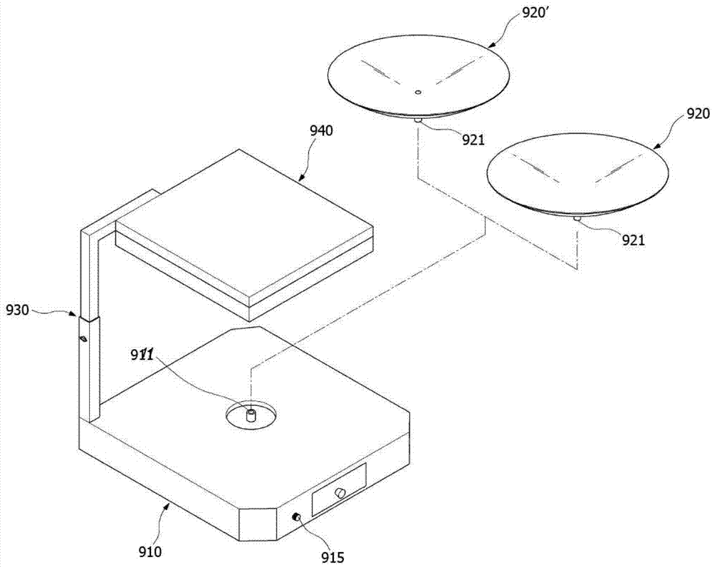
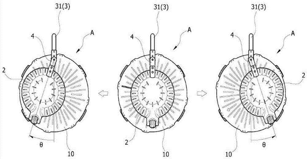
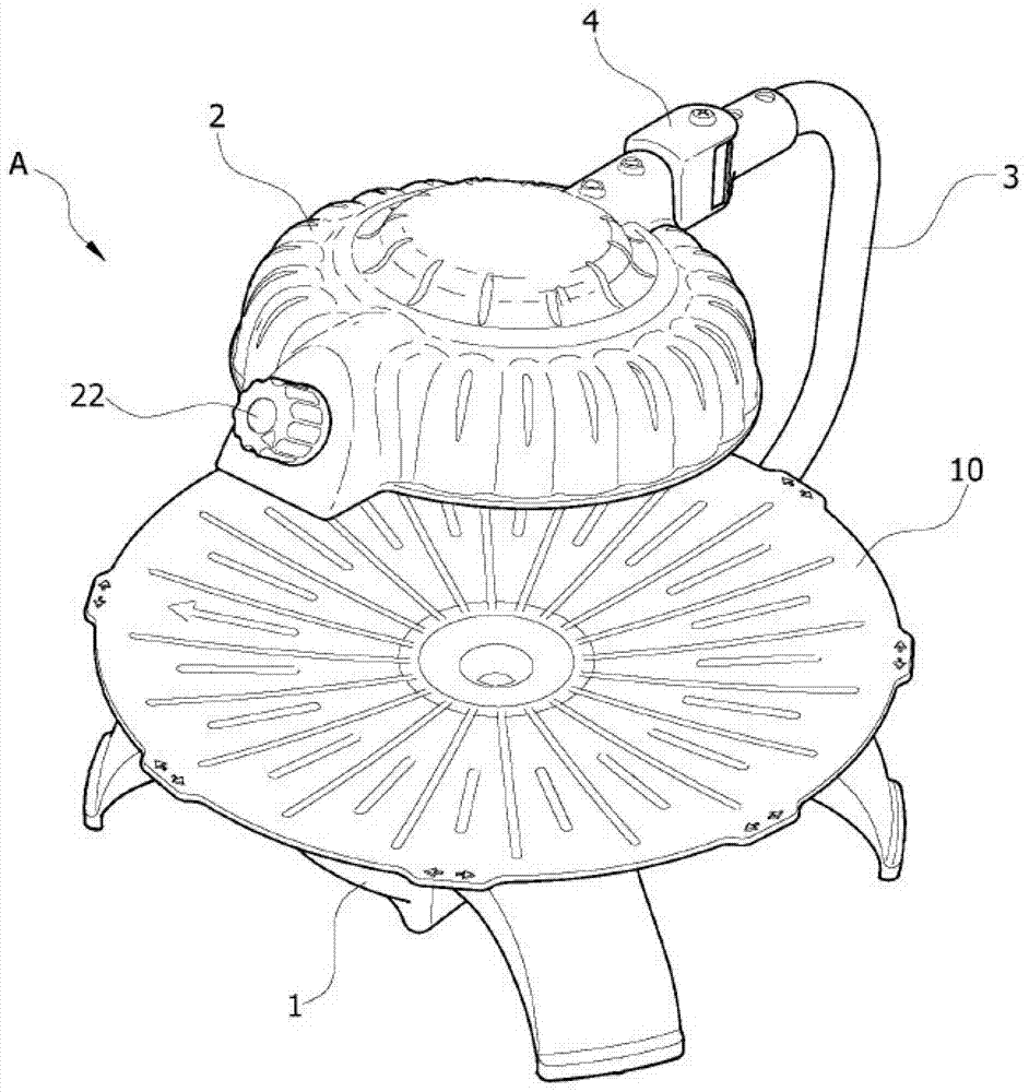
[0031] In the attached picture figure 2 and image 3 It is a perspective view and a side view illustrating the overall structure of an infrared heating cooker with a variable heating head position according to the present invention, Figure 4 It is a partial enlarged cross-sectional view illustrating the combined relationship of...


PUM


Abstract

The invention discloses an infrared cooking device with a variable heating head position. Through horizontal rotation of a heating head which irradiates heat from top to bottom, temperature difference between different areas of a cooking dish which is configured below the heating head is maximally reduced. Furthermore a rotation limit is kept for restricting the rotating area of the heating head, and furthermore action of a heat source can be automatically stopped according to the requirement.

Description

technical field [0001] The present invention relates to an infrared cooker, in particular to an infrared cooker with a variable heating head position, which minimizes the distance between each area of ​​the cooking plate arranged below it through the horizontal rotation of the heating head that irradiates the heat source from top to bottom. In addition, there is an end of rotation to limit the rotation area of ​​the above-mentioned heating head, and the action of the heat source can be automatically interrupted as needed. Background technique [0002] With people's awareness of the disadvantages of modern industrial society, the need to create a happier life through the harmony of spiritual and physical health has increased, and Well-being has become a new trend that dominates our society. In this way, in order for me and my family to enjoy a healthy life of "eating well and living well", it is only natural that we need to take care of the environment we will live in in the ...

Claims


Application Information

Patent Timeline
IPC IPC(8): A47J37/04
CPCA47J37/04A47J36/24F24C7/06F24C15/08H05B3/00A47J36/2488A47J37/046F24C7/067F24C15/086H05B3/0076
Inventor 李琎熙
Owner ZAIGLE CO LTD
Why Eureka
Try Eureka