
Manufacturing method for 3 printing core with direct-cooling chilling block

A technology of 3D printing and direct cooling cold iron, which is applied in the direction of cores, manufacturing tools, casting molding equipment, etc., can solve the problems of large installation gaps, direct cooling cold irons are easy to fall off, etc., and achieve the effect of preventing weak bonding

Active Publication Date: 2017-06-20
共享智能铸造产业创新中心(潍坊)有限公司
View PDF7 Cites 20 Cited by
  • Summary
  • Abstract
  • Description
  • Claims
  • Application Information

AI Technical Summary

Problems solved by technology

[0003] The present invention aims at the problems existing in the chill placement process of 3D printing sand cores with direct cooling chills in the prior art, and provides a manufacturing method for 3D printing sand cores with chills to solve the problem that the direct cooling chills are easy to fall off. The problem of large installation gaps

Method used


Image

  • Manufacturing method for 3 printing core with direct-cooling chilling block
  • Manufacturing method for 3 printing core with direct-cooling chilling block
  • Manufacturing method for 3 printing core with direct-cooling chilling block

Examples


Embodiment Construction

[0015] The manufacturing method of the 3D printing sand core with direct cooling iron of the present invention will be described in detail below in conjunction with the accompanying drawings.

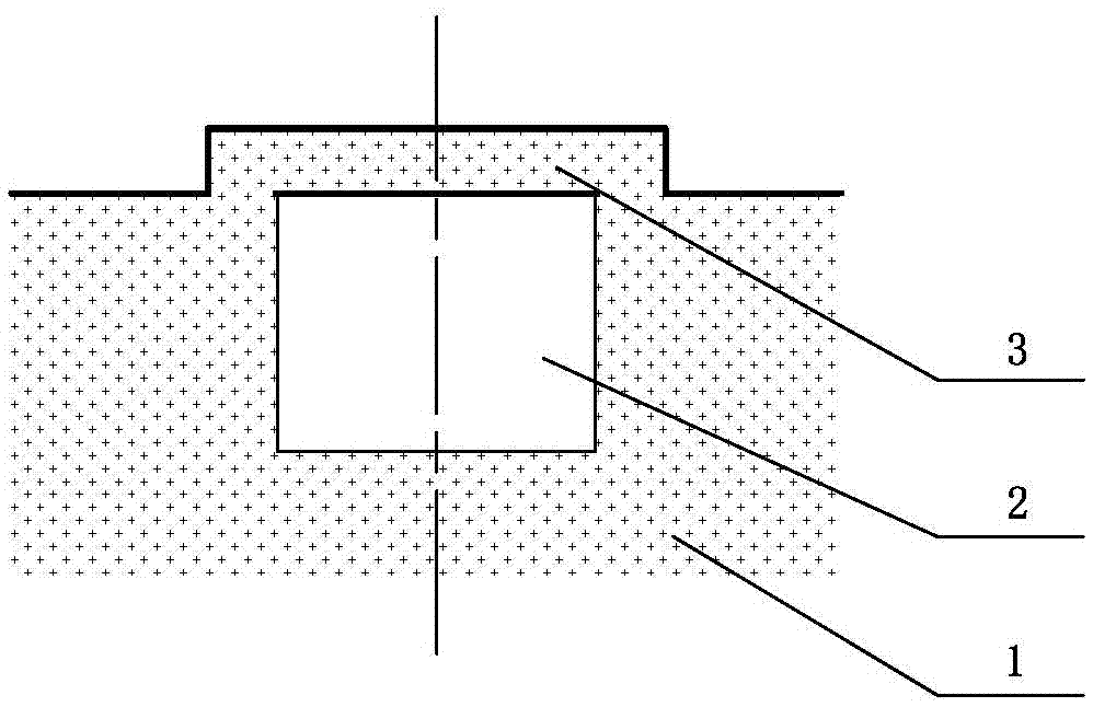
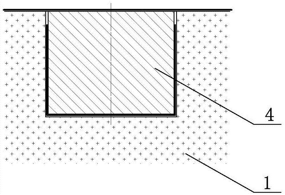
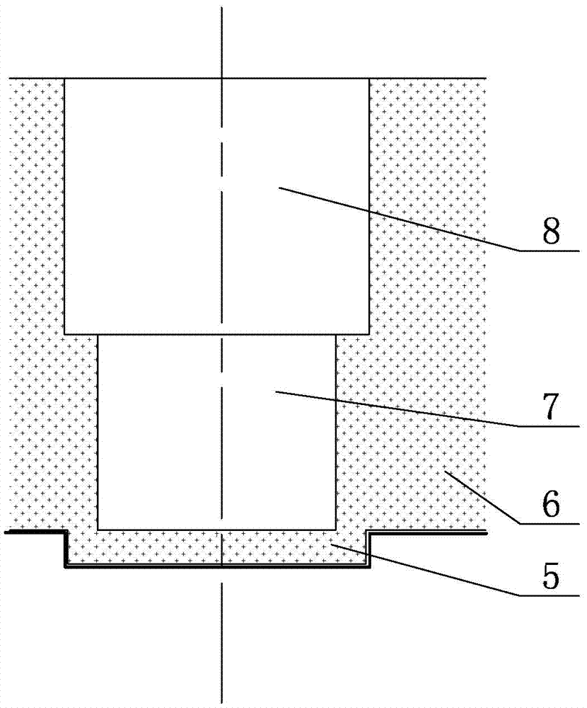
[0016] Such as figure 1 — Figure 5 As shown, the manufacturing method of the 3D printing sand core with direct cooling chill iron of the present invention includes the following processes in sequence: core structure design, sand core 3D printing, sand core flow coating, and chill iron installation.

[0017] Such as figure 1 shown and image 3 As shown, during the design process of the sand core structure, the corresponding part of the sand core that needs to be installed with the chiller is designed to match the pit for installing the chiller. The pit corresponds to the opening of the casting and is provided with a protruding sand core that is integrally formed with the sand core. Sealing cap corresponding to casting profile. In this embodiment, the direct-cooled chills used for 3D...


PUM

PropertyMeasurementUnit
Thicknessaaaaaaaaaa

Abstract

The invention relates to the technical field of casting, in particular to a manufacturing method which is high in manufacturing precision and capable of improving the casting quality and is provided with a direct-cooling chilling block and used for a 3D printing core. The manufacturing method sequentially comprises the following procedures of core structure designing, core 3D printing and core flow painting. The manufacturing method is characterized in that in the core structure designing process, a pit for installing the chilling block in a matched manner is designed on a core part needing the chilling block to be arranged, and a sealing cover which is integrally formed with the core and protrudes a casting outline corresponding to the core is arranged at the position, corresponding to a casting opening, of the pit; in the core 3D printing process, the core with the sealing cover is printed through 3D printing equipment; and then, core flow painting is carried out, after a flow coating layer on the surface of the core is dried, chilling block is installed, during installation, the protruding sealing cover is polished so that an opening, corresponding to the casting side, of the pit can be exposed, sand in the pit is removed, then, the chilling block is arranged in a matched manner and fixed into the pit, finally, a fire-proof coating is painted to the exposed chilling block end face in a supplementation manner, and manufacturing of the 3D printing core with the chilling block is completed.

Description

technical field [0001] The invention relates to the technical field of making casting sand cores, in particular to a method for making 3D printing sand cores with direct cooling irons. Background technique [0002] With the promotion and application of 3D printing technology, the current method of using 3D printing sand cores for casting production has gradually become popular in the industry. This method does not need to consider the problems of mold removal and material removal similar to traditional processes, and can realize one-time high-precision printing of sand cores with various complex structures, greatly improving the flexibility of casting process design. During the pouring of ductile iron castings, due to the transformation of the metallographic structure during the solidification process, it is difficult for the grain gap to be fully replenished by molten iron, so shrinkage and shrinkage are more likely to occur than gray iron. In the process design, it is nec...

Claims


Application Information

Patent Timeline
IPC IPC(8): B22C9/10B33Y10/00B22D27/04
CPCB22C9/10B22D27/04B33Y10/00
Inventor 杜文强李嘉豪
Owner 共享智能铸造产业创新中心(潍坊)有限公司
Learn More