Method and device to reduce residual stress of boards during friction stir welding
A friction stirring and residual stress technology, applied in welding equipment, non-electric welding equipment, metal processing equipment, etc., to eliminate residual stress, improve performance, and reduce production costs
- Summary
- Abstract
- Description
- Claims
- Application Information
AI Technical Summary
Problems solved by technology
Method used
Image
Examples
Embodiment 1
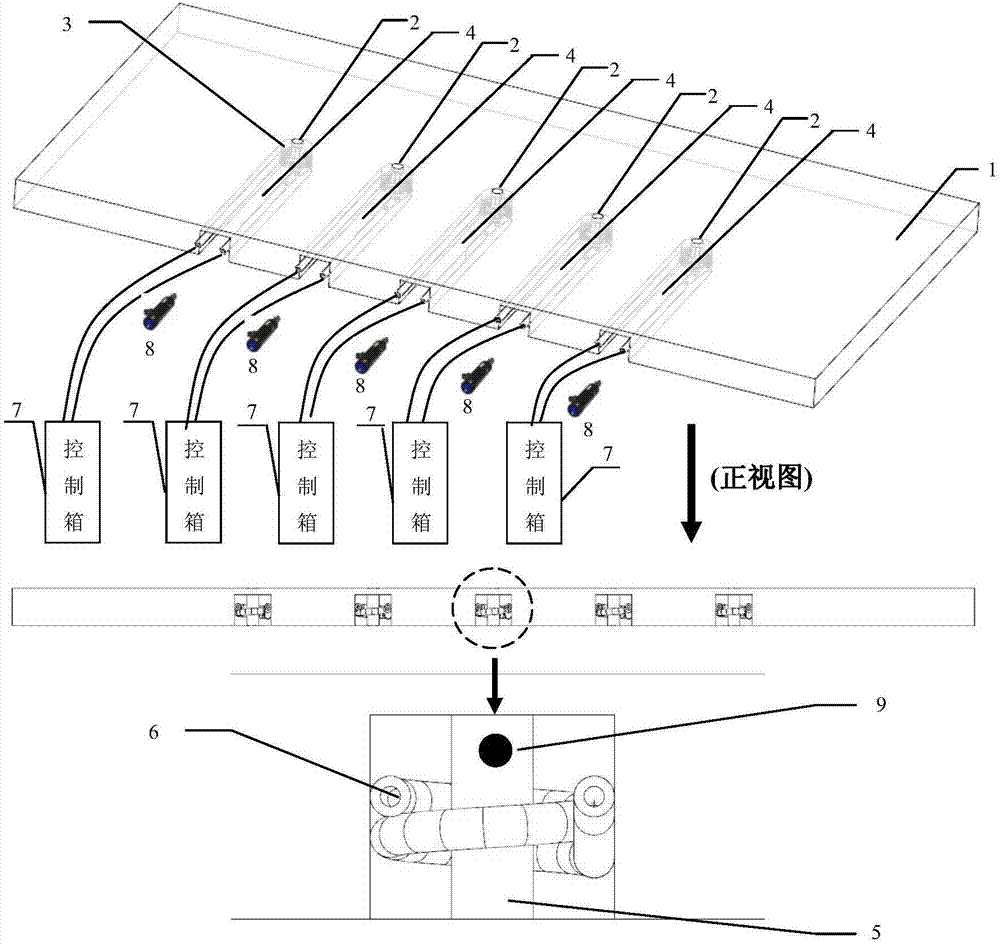
[0026] Such as figure 1 shown.
[0027] A method for reducing the residual stress of friction stir welded plates, the key of which is to set a number of heat source points on the backing plate for friction stir welding relative to the weld seam, and the heat source points are heated by high-frequency induction coils to generate heat, so that the heat source points The generated heat source matches the heat generated by the friction stir welding process, and maintains the heat until the end of the entire welding process, reduces the temperature gradient between the welding area of the stirring head and the welded area, and controls the heat output of the heat source after the welding is completed , to keep the welded plate warm, to eliminate the mechanical residual stress in the joint, reduce and eliminate the residual stress of the welded joint. The details are as follows:
[0028] 1. Select the heat source point 2 along the center line of the length direction on the steel...
Embodiment 2
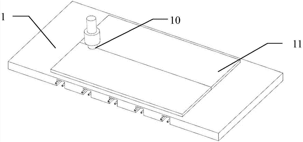
[0033] Such as Figure 1-2 shown.
[0034] A device used in friction stir welding to reduce / eliminate the residual stress of friction stir welded plates, which includes a steel backing plate 1 (it can also be a titanium alloy plate, a tungsten alloy plate, a molybdenum alloy plate and other metal material plates), Such as figure 1As shown, the size of backing plate 1 is 800mm×400mm×30mm. Five circular areas are selected on the backing plate 1 along the center line in the length direction as heat source points 2. The diameter of the circular area is 10mm, and the middle heat source point 2 is located on the backing plate. In the geometric center of the surface, five heat source points 2 are arranged in a "one" shape, and the distance between two heat source points 2 is 100mm (can also be selected between 5mm-500mm); the heat of heat source point 2 comes from the high-frequency induction coil Heating the cylindrical iron core 5 generates heat conduction, and the time required ...
PUM
| Property | Measurement | Unit |
|---|---|---|
| Diameter | aaaaa | aaaaa |
| Outer diameter | aaaaa | aaaaa |
| The inside diameter of | aaaaa | aaaaa |
Abstract
Description
Claims
Application Information
 - R&D
- Intellectual Property
- Life Sciences
- Materials
- Tech Scout
- Unparalleled Data Quality
- Higher Quality Content
- 60% Fewer Hallucinations
Browse by: Latest US Patents, China's latest patents, Technical Efficacy Thesaurus, Application Domain, Technology Topic, Popular Technical Reports.
© 2025 PatSnap. All rights reserved.Legal|Privacy policy|Modern Slavery Act Transparency Statement|Sitemap|About US| Contact US: help@patsnap.com


