

Method and device for effectively reducing or eliminating residual stress of friction stir welding plate
A friction stir and residual stress technology, used in welding equipment, process efficiency improvement, non-electric welding equipment, etc., can solve problems such as residual stress of welded plates, and achieve the effect of improving performance, high-quality friction stir welding, and reducing production costs.
- Summary
- Abstract
- Description
- Claims
- Application Information
AI Technical Summary
Problems solved by technology
Method used
Image

Examples
Embodiment 1
[0027] Such as figure 1 shown.
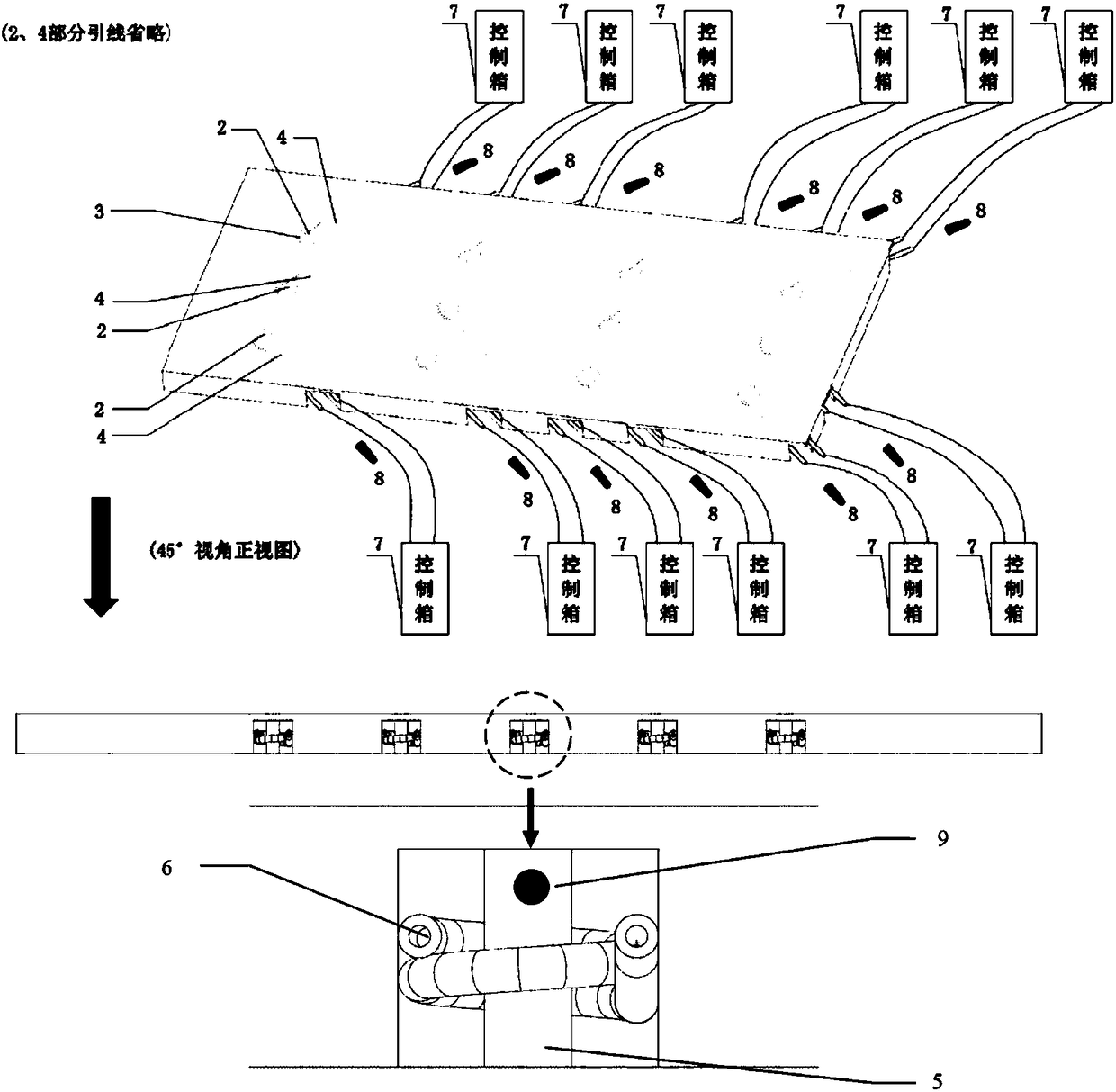
[0028] A method that can effectively reduce / eliminate the residual stress of friction stir welded plates, the key of which is to set a number of heat source points at the position opposite to the weld seam and on both sides of the backing plate for friction stir welding to form an array arrangement, each heat source The point uses high-frequency induction coil heating to generate heat, so that the heat source generated by the heat source point matches the heat generated by the friction stir welding process. Its array point heat source can produce different residual stress for different types of plates due to different material properties. Control and maintain a certain amount of heat until the end of the entire welding process, reduce the temperature gradient between the welding area of the stirring head and the welded area, after the welding is completed, control the heat production of the heat source, keep the welding plate warm, and elimin...
Embodiment 2
[0035] Such as figure 1 shown.
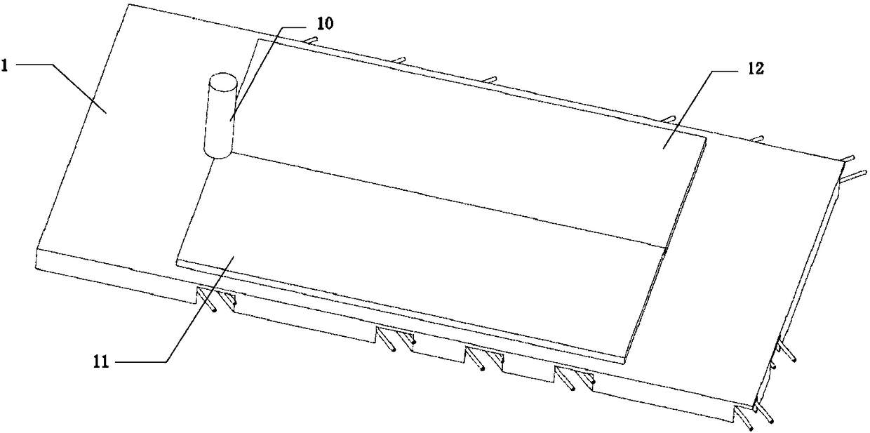
[0036] It is used in friction stir welding and can effectively reduce / eliminate the residual stress of friction stir welding plates, which includes a steel backing plate 1 (it can also be a titanium alloy plate, a tungsten alloy plate, a molybdenum alloy plate and other metal dissimilar material plates) ,Such as figure 1 As shown, the size of the backing plate 1 is 800mm×400mm×30mm. On the backing plate 1, 12 circular areas are selected as the heat source points 2 along the center line of the length direction and on both sides. The diameter of the circular area is 10mm. The heat source point in the middle 2 Located at the geometric center of the surface of the backing plate, 12 heat source points 2 are arranged in an array, and the distance between the two heat source points 2 is 100mm (can also be selected between 5mm-500mm); the heat of heat source point 2 comes from high frequency The induction coil heats the cylindrical iron core 5 to gen...
PUM
| Property | Measurement | Unit |
|---|---|---|
| Diameter | aaaaa | aaaaa |
| Outer diameter | aaaaa | aaaaa |
| The inside diameter of | aaaaa | aaaaa |
Abstract
Description
Claims
Application Information