Table vibration building block forming machine capable of manufacturing height being 500 mm

A block forming machine and forming mechanism technology, applied in the direction of ceramic forming machines, forming pressure heads, auxiliary forming equipment, etc., can solve the problem that the overall height of the lifting drive device cannot be made very high, and the lifting stroke cannot be too short or too long , unable to simultaneously lift and lower both sides of the pressure head, etc., to achieve the effect of wide setting range, good molding quality, and stable lifting

Active Publication Date: 2017-06-20
FUJIAN QUNFENG MACHINERY
View PDF9 Cites 3 Cited by
  • Summary
  • Abstract
  • Description
  • Claims
  • Application Information

AI Technical Summary

Problems solved by technology

However, in the existing table vibration block forming machines, the lifting drive device for the up and down lifting and demoulding of the molding frame adopts the mode of the oil cylinder and the straight arm plate, that is, the oil cylinder and the straight arm are on the same straight line, which causes the lifting drive device The overall height is very high, and it takes up a lot of space during operation. For production safety, the overall height of the lifting drive device cannot be made very high, that is, the length of the straight arm plate is relatively short. The stroke cannot be too short or too long. The limitation of the lifting stroke of the forming mold frame makes the brick-making range of the forming mold frame generally only between 250-400mm, and it is impossible to form high bricks; It is easy to produce deflection, and it is impossible to make the two sides of the pressure head rise and fall synchronously, so that the formed blocks have high and low phenomena and uneven defects

Method used


Image

  • Table vibration building block forming machine capable of manufacturing height being 500 mm
  • Table vibration building block forming machine capable of manufacturing height being 500 mm
  • Table vibration building block forming machine capable of manufacturing height being 500 mm

Examples


Embodiment Construction

[0019] The present invention will be further described below in conjunction with the accompanying drawings and specific embodiments.

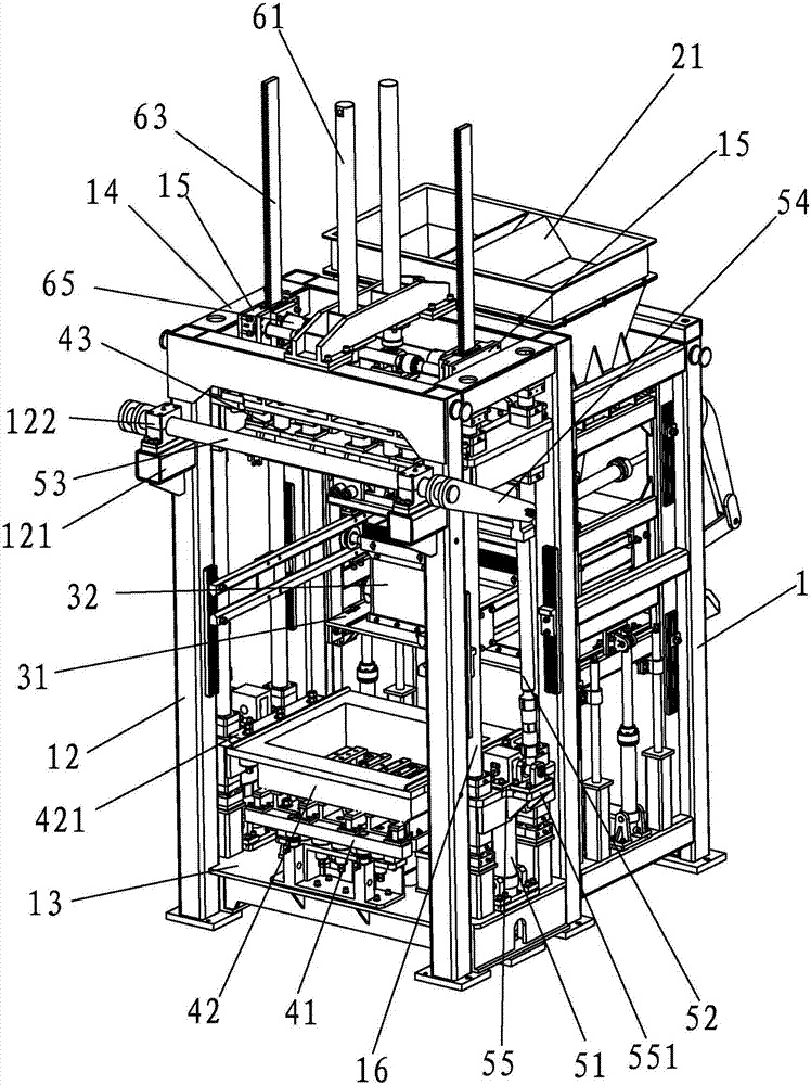
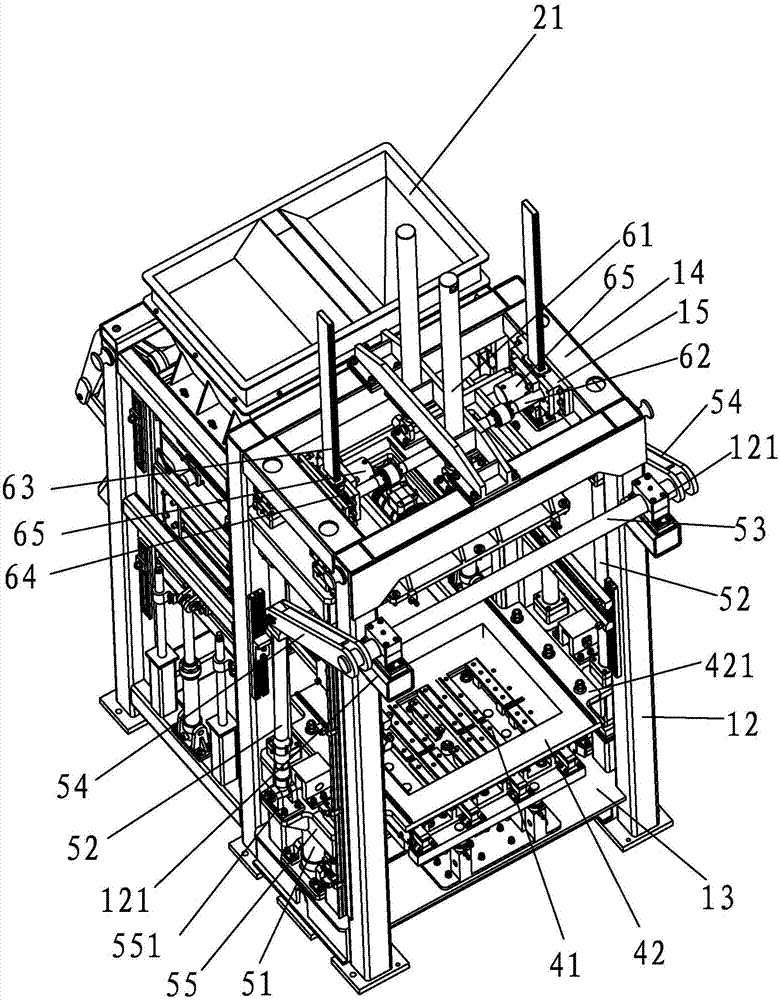
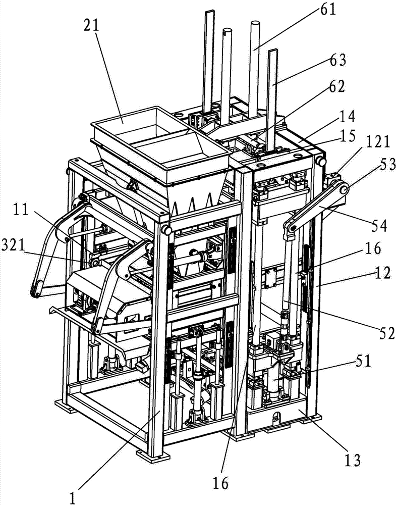
[0020] A kind of 500mm high table vibration block forming machine of the present invention, such as Figure 1-4 As shown, it includes the frame 1 and the unloading mechanism, the material distribution mechanism and the forming mechanism in the frame 1. The unloading mechanism includes a hopper 2 and a control structure that controls the opening or closing of the outlet of the hopper 2 below the hopper 2. (not marked in the figure), the hopper 2 is above the rear portion of the frame, and what this feeding mechanism adopts is a known technology, which will not be repeated here. The feeding mechanism is directly below the feeding mechanism, and the feeding mechanism includes The bottom plate 31 is laid flat on the cloth trolley 32 on the bottom plate 31. The bottom plate 31 is fixed on the frame 1, and the cloth trolley 32 is movable and installe...


PUM


Abstract

The invention provides a table vibration building block forming machine capable of manufacturing the height being 500 mm. The table vibration building block forming machine comprises a rack, a discharging mechanism, a distributing mechanism and a forming mechanism. A first lifting drive device and a second lifting drive device are mounted on the rack. The first lifting drive device comprises first oil cylinders connected with a forming mold frame, vertical rods located above the first oil cylinders, connecting arms obliquely located above the vertical rods and a mounting rod connected with the connecting arms and the rack. The second lifting drive device comprises second oil cylinders, a rotary shaft, gear racks and gears. The second oil cylinders are connected with a press head. The gear racks and the press head are arranged. The gears are mounted on the rotary shaft. The gears and the gear racks are correspondingly engaged. An abutting mechanism for abutting against the gear racks to keep a vertical state all the time is arranged on the rack. According to the table vibration building block forming machine, high bricks ranging from 180 mm to 500 mm can be formed; the overall size is small; the press head ascends and descends stably; the surfaces of the formed high bricks are smooth, and high-low bricks are avoided; and the demolding speed is high and stable.

Description

technical field [0001] The invention relates to brick-making machinery, in particular to a platform vibrating block forming machine. Background technique [0002] At present, the concrete block forming machine can be divided into two types according to the vibration form. One is the table vibration block forming machine. The vibration source is not directly connected to the mold, but the vibration energy is transmitted through the vibration table located under the mold. (Taiwan vibration); the other is the mold vibration block forming machine, which is directly transmitted to the vertical one-way vibration (mode vibration) of the mold box through the vibration source connected to the mold; wherein, the mold vibration block forming machine is due to the The plate area is relatively small, and the product varieties formed are single (mainly concentrated in hollow blocks), while the Taizhen block forming machine has a large pallet area, a variety of formed products, and a wide ...

Claims


Application Information

Patent Timeline
IPC IPC(8): B28B3/04B28B1/087B28B7/00B28B17/00
CPCB28B1/087B28B3/022B28B3/04B28B7/0097B28B17/00
Inventor 徐金山林阿勇
Owner FUJIAN QUNFENG MACHINERY
Why Eureka
Try Eureka