
Robot for cleaning particle materials

A technology for cleaning robots and granular materials, applied in the field of food machinery, can solve the problems of high labor intensity, low work efficiency, and a lot of human labor, and achieve the effect of flexible working methods and high degree of automation

Pending Publication Date: 2017-06-20
江苏新宝物流机器人有限责任公司
View PDF5 Cites 5 Cited by
  • Summary
  • Abstract
  • Description
  • Claims
  • Application Information

AI Technical Summary

Problems solved by technology

[0003] Aiming at the problems that a large amount of manpower is required in the operation process of bulk granular materials, labor intensity is high, and work efficiency is low, the present invention provides a cleaning robot with a reasonable structure, which can automatically collect bulk materials into piles or spread them to both sides to realize digging. , Grilling, sweeping, cleaning and other all-round automatic cleaning operations, effectively improving cleaning efficiency

Method used


Image

  • Robot for cleaning particle materials
  • Robot for cleaning particle materials
  • Robot for cleaning particle materials

Examples


Embodiment 1

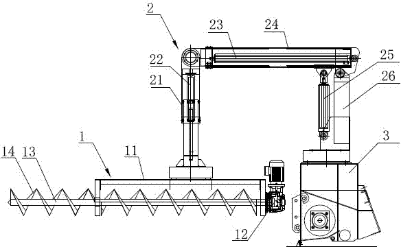
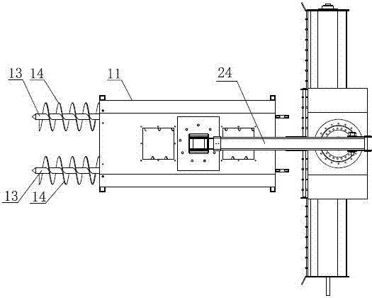
[0022] Such as figure 1 , figure 2 As shown, the granular material cleaning robot includes a manipulator 1, an arm 2 and a base 3. The manipulator 1 includes a cuboid shell 11 with an open bottom, and two core rods 13 are arranged in parallel inside the shell 11, and two core rods 13 are provided with spiral directions. Opposite helical blades 14 . The length of the core rod 13 is longer than the length of the shell 11, the end is driven by the drive motor 12, and the front end part away from the base 3 extends out of the shell 11, and the extension part can be screwed into the pile of hardened and agglomerated materials during work, playing a role similar to The function of the drill bit to break the hardened area of ​​the material. The length of the core rod 13 extending out of the shell 11 is 0.5 times the length of the shell 11 , and in other embodiments the length of the core rod 13 extending out of the shell 11 may also be 0.1-0.8 times the length of the shell 11 .

...

Embodiment 2

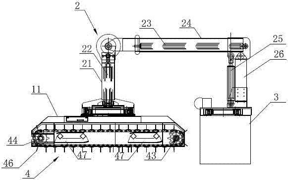
[0026] Such as image 3 , Figure 4 As shown, in this embodiment, the manipulator 1 is replaced by a scraper conveyor 4. The scraper conveyor 4 includes a cuboid shell 11, and two parallel sprocket shafts 42 are longitudinally arranged at both ends of the shell 11. On the two sprocket shafts 42 Drive sprocket 43 and driven sprocket 44 are arranged respectively, and two parallel chains 45 are perpendicular to sprocket shaft 42 and are enclosed within on drive sprocket 43 and driven sprocket 44, are provided with some vertical sprockets on two chains 45. scraper 46. One end of the drive sprocket 43 on the casing 11 is provided with a transmission mechanism 41 for driving the drive sprocket 43 to rotate. Two brackets 47 are also arranged between the driving sprocket 43 and the driven sprocket 44 in the housing 11, and the brackets 47 are used to support the chain 45 and connect the housing.

[0027] During actual work, start the transmission mechanism 41 of the scraper conveyo...


PUM


Abstract

The invention discloses a robot for cleaning particle materials. The robot comprises a mechanical arm, an arm portion and a base. The bottom of the mechanical arm is opened, and a conveying mechanism is arranged inside the bottom of the mechanical arm. The mechanical arm is connected to the head end of the arm portion through a connection joint. The tail end of the arm portion is mounted on the base. According to the mechanical arm of the robot for cleaning the particle materials, augers in parallel connection or a scraper conveyer is adopted, materials can be scattered or collected to be piled, and the work mode is flexible. The front end auger of the parallel-connection auger mechanical arm extends out of an outer shell of a screw conveyer, the materials in a material storage bin can be directly rotated therein, and an arch formed by the materials is damaged. According to the robot, the rotatable connection joint is extended, retracted and rotated through all oil cylinders of the arm portion of the mechanical arm, the operation space position of the cleaning robot can be adjusted flexibly, thus the materials can be leveled and cleared within a larger range and in any direction, and the automation degree is high.

Description

technical field [0001] The invention relates to the field of grain machinery, in particular to a cleaning robot for bulk granular materials. Background technique [0002] At present, the cleaning operations of bulk materials in warehouses such as flat warehouses, flat-bottomed round silos and large ship cabins are basically completed by manpower. There are more than 100 billion catties of grain in China every year. In specific seasons, it needs to be spread, collected and stored. Simply relying on human labor, the labor load is large, the work efficiency is low, and the quality of grain spread is often affected due to untimely cleaning and recovery. even cause losses. Moreover, the processing and transportation of bulk materials are often accompanied by a large amount of organic and inorganic dust that is harmful to human health. When the silica content in the dust exceeds 1%, it is very harmful to the human body. If the storage is rice husk, soybean meal and other oil cro...

Claims


Application Information

Patent Timeline
Patent Type & Authority Applications(China)
IPC IPC(8): B65G65/28B65G65/22B65G65/06B65G69/04B65D88/68B65D88/64
CPCB65D88/64B65D88/68B65G65/06B65G65/22B65G65/28B65G69/0416B65G69/0433B65G2201/042
Inventor 王荀
Owner 江苏新宝物流机器人有限责任公司
Learn More