Liquor distilling device

A technology for steaming wine and fermented grains, which is applied in the preparation of alcoholic beverages and other directions, can solve the problems of mixing and affecting the quality of wine, and achieve the effects of reducing the temperature of wine, reducing impurities with high boiling points, and improving the rate of wine production.

Inactive Publication Date: 2017-06-20
RUIAN MAITENG ELECTRONICS COMMERCE CO LTD
View PDF0 Cites 2 Cited by
  • Summary
  • Abstract
  • Description
  • Claims
  • Application Information

AI Technical Summary

Problems solved by technology

On the other hand, as the distillation process proceeds, the temperature of the fermented grains continues to rise, and some impurities with high boiling points are gradually distilled out, mixed into the wine vapor, and affect the quality of the wine.

Method used


Image

  • Liquor distilling device
  • Liquor distilling device
  • Liquor distilling device

Examples


Embodiment 1

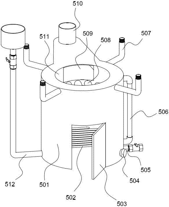
[0034] Such as Figure 1-5 As shown, this embodiment includes a steam generator 501 for generating the water vapor required for heating the fermented grains, a distilling barrel 400 for containing the fermented grains, a sky pot condenser 300 covering the distilling vat 400, and a steamer for distilling A blower and an air duct for blowing air into the bucket 400 .

[0035] Such as figure 1As shown, the steam generator 501 is a steam boiler, the furnace body of the steam boiler is an annular water tank, the inner side of the inner wall 511 of the annular water tank is a furnace, the furnace bridge 502 is arranged below the furnace, and a plurality of tubes and the inner wall of the annular water tank are arranged above the furnace. 511 welded heat exchange tubes 508, the inner space of the heat exchange tubes 508 communicates with the inner space of the annular water tank, and the inner space of the annular water tank and the inner space of the heat exchange tubes 508 togethe...

Embodiment 2

[0045] refer to figure 1 , figure 2 , image 3 , Image 6 , the present embodiment includes a steam generator 501 for generating the water vapor required for heating the fermented grains, a distilling barrel 400 for containing the fermented grains, a sky pot condenser 300 covering the distilling vat 400, and a steam generator 500 for feeding the distilling vat 400 The air blower, the air guide pipe and the air guide circuit pipe are blown into the air.

[0046] The structure reference of steam generator 501 figure 1 Shown and written description of Example 1.

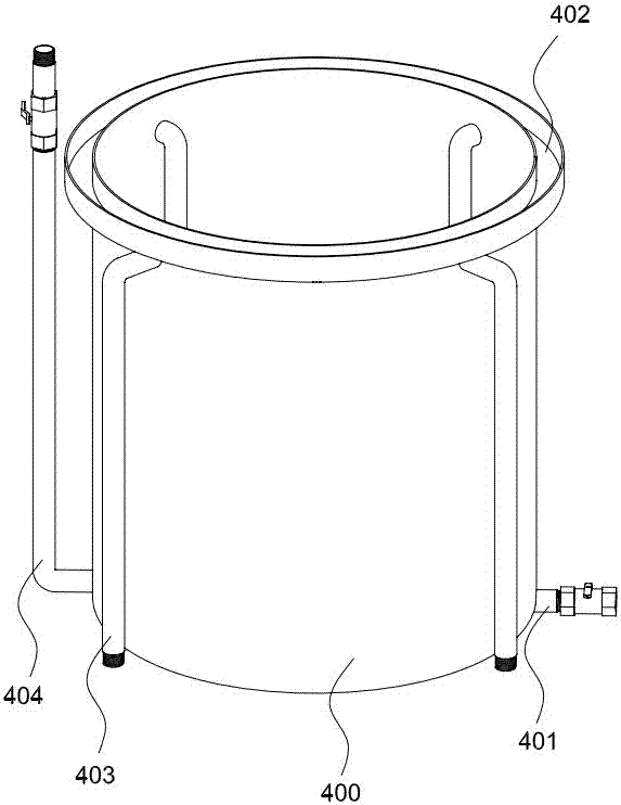
[0047] Structural reference of distillation barrel 400, blower and air duct figure 2 , image 3 Shown and written description of Example 1.

[0048] Such as Image 6As shown, the sky pot condenser 300 includes a retort 301 whose shape is similar to the side of a circular platform, and whose upper end is slightly smaller than the lower end. There is a circular cover plate 309 on the upper end of the retort 301...

Embodiment 3

[0050] This embodiment includes a steam generator 501 for generating the water vapor required for heating the fermented grains, a still barrel 400 for containing the fermented grains, a sky pot condenser 300 that covers the still barrel 400, and a steam generator 500 for feeding the fermented grains into the still barrel 400. Air blower, air duct.

[0051] The steam generator 501 of the present embodiment refers to figure 1 Shown and written description of Example 1.

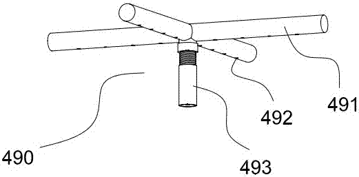
[0052] The structure of the distillation barrel of this embodiment is similar to that of the first embodiment, the only difference is that the distillation barrel of this embodiment does not have such figure 2 The "L" shaped airway 404 shown and image 3 Air distribution tube 490 is shown.

[0053] Such as Figure 7 As shown, the air guide pipe in this embodiment includes a distillation barrel side air guide pipe, and the distillation barrel side air guide pipe includes a fixed pipe 322 and a detachable pip...


PUM


Abstract

The invention discloses a liquor distilling device. The liquor distilling device comprises a steam generator, a distillation cylinder and an upper pot condenser. The steam generator is a steam boiler, and the steam boiler is provided with a steam generation space for containing water and steam, and multiple lower half section steam conduits communicating with the steam generation space. The space containing fermented grains on the inner side of the distillation cylinder is a fermented grain distillation space, and multiple upper half section steam conduits are arranged on the wall of the distillation cylinder. One end of each upper half section steam conduit communicates with the fermented grain distillation space, and the other end of each upper half section steam conduit is detachably connected with the upper end of the corresponding lower half section steam conduit. The upper half section steam conduits and the lower half section steam conduits jointly form steam conduits connecting the steam generation space with the fermented grain distillation space. The liquor distilling device is further provided with an air guiding pipeline and an air blower, wherein one end of the air guiding pipeline communicates with the fermented grain distillation space, and the other end of the air guiding pipeline is connected with an air outlet of the air blower.

Description

technical field [0001] The invention relates to the field of brewing equipment, in particular to a wine steaming equipment. Background technique [0002] Existing wine steaming equipment can be divided into two major classes according to its working principle, and a class is direct heating type, and another kind is indirect heating type. The direct heating type wine steaming equipment uses firepower or electricity to directly heat the wine grains to generate wine steam, and then condenses the wine steam to obtain distilled wine. The indirect heating type wine distillation equipment first uses firepower or electricity to heat water to obtain water vapor, and then uses the water vapor to heat the wine grains to generate wine vapor, which is condensed to obtain distilled wine. The direct heating type wine steaming equipment has the advantages of simple structure and low cost, but at the same time, it has the defect that it is easy to stick to the pot; the indirect heating type...

Claims


Application Information

Patent Timeline
Patent Type & Authority Applications(China)
IPC IPC(8): C12G3/12C12H6/02
CPCC12H6/02
Inventor 不公告发明人
Owner RUIAN MAITENG ELECTRONICS COMMERCE CO LTD
Why Eureka
Try Eureka