Continous Heating Device For Coil Springs And Heating Method For Coil Springs By Using This Device

A technology of coil springs and heating devices, applied in the direction of induction heating devices, springs, coil devices, etc., can solve the problems of unsuitable manufacturing of small coil springs, complex structure of continuous heating devices, complicated spring input process, etc., to improve quality and reliability The effect of high performance, simple structure and smooth power transmission

Active Publication Date: 2017-06-20
DAEWON APPLIED ENG CO
View PDF4 Cites 4 Cited by
  • Summary
  • Abstract
  • Description
  • Claims
  • Application Information

AI Technical Summary

Problems solved by technology

However, the above-mentioned device has the problem that the insertion process of the spring is complicated, and a complicated mechanical structure is required, and the productivity cannot be greatly improved.
[0012] In addition, U.S. Patent No. 8912472 discloses a device in which a coil spring is rotated on a pair of rotating rollers arranged in parallel and rotated in the same direction, and the coil spring is heated by induction heating. However, when When the coil spring is dropped vertically downward on the rotating roller, the coil spring may pop out due to the movement of the rotating roller, and the rotating roller needs to be extended to both sides every time the coil spring is lowered. , therefore, there is a problem that the structure of the continuous heating device becomes complicated and it is difficult to improve productivity.
[0013] Moreover, in the above-mentioned heating device, the structure in which the coil spring is dropped from the top to the bottom on the rotating roller is suitable for a large coil spring, so there is a problem that it is not suitable for the production of a small coil spring.

Method used


Image

  • Continous Heating Device For Coil Springs And Heating Method For Coil Springs By Using This Device
  • Continous Heating Device For Coil Springs And Heating Method For Coil Springs By Using This Device
  • Continous Heating Device For Coil Springs And Heating Method For Coil Springs By Using This Device

Examples


Embodiment Construction

[0047] It should be noted that the terms used in this specification are only used to describe specific embodiments, and are not used to limit the present invention.

[0048] Moreover, as long as there is no special definition in other meanings in this specification, the technical terms used in this specification should be understood as the meanings commonly understood by those of ordinary skill in the technical field to which the present invention belongs, and should not be interpreted in an overly broad sense. to be interpreted, or should not be interpreted in an overly narrowed sense.

[0049] In addition, as long as different meanings are not clearly indicated in the context, expressions of the singular number used in this specification include expressions of the plural number. In this application, terms such as "consisting" or "comprising" should not be interpreted as necessarily including various structural elements or multiple steps described in the specification, but sh...


PUM


Abstract

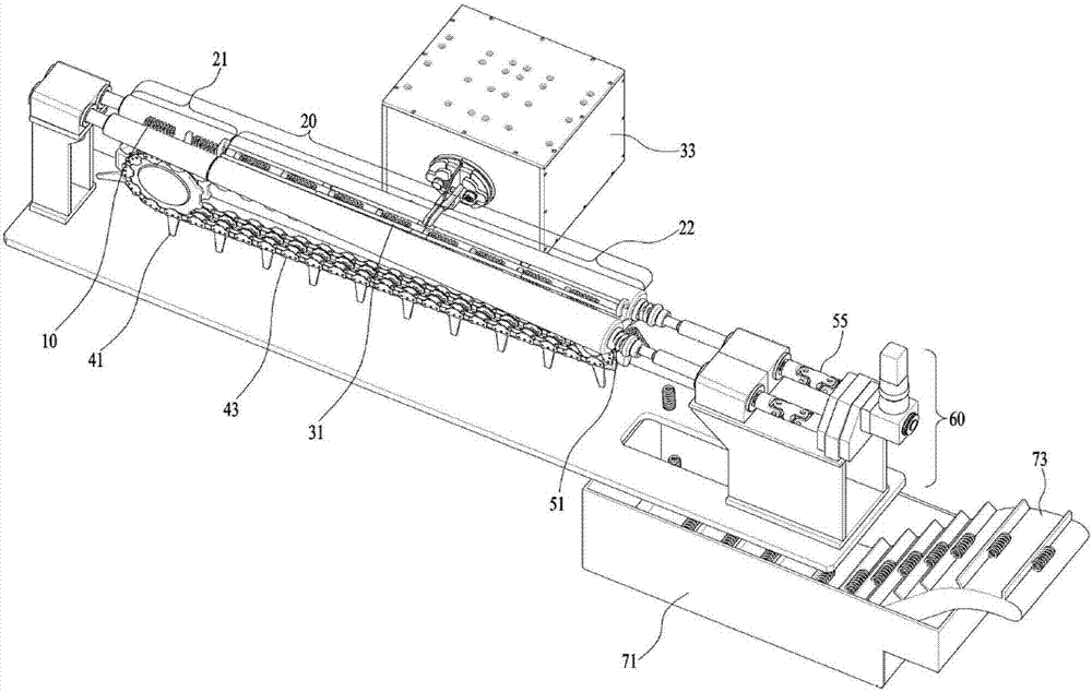
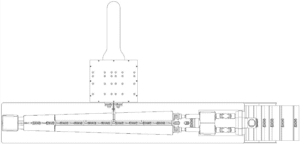
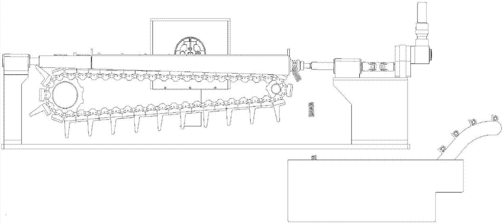
The present invention relates to a continuous heating device for coil springs and a continuous heating method for coil springs using the same. The device may include: a pair of tapered rollers configured to support and rotate the coil spring, configured to have a cross-sectional diameter that increases as it goes from the front end portion to the rear end portion, and configured to have rotational inner surfaces that are arranged to be parallel with each other while the central rotation axes thereof are not parallel with each other; a conveyor chain configured to have a push rod that is installed therein to move the coil spring; and a driving unit configured to provide a rotational driving force to the pair of tapered rollers. The method may include: inputting and rotating a coil spring by means of a pair of tapered rollers such that the coil spring does not pop out of the tapered rollers, the tapered rollers having a cross-sectional diameter that increases as it goes from the front end portion to the rear end portion and having rotational inner surfaces that are arranged to be parallel with each other while the central rotation axes thereof are not parallel with each other; moving the coil spring by means of a conveyor chain that has a push rod installed therein; and heating the coil spring by a high-frequency induced magnetic field while rotating the coil spring by using the tapered rollers in the section of an electric induction coil.

Description

technical field [0001] The present invention relates to a coil spring continuous heating device for heating a coil spring formed by processing a spring steel wire rod into a coil shape, and more specifically, to the following coil spring continuous heating device and a coil spring continuous heating method using the same, That is, it is provided that the coil spring is continuously heated by an electric induction heating process in which the coil spring is not directly brought into contact with a heat source while gradually increasing the rotation speed of the coil spring with a tapered roller and moving the coil spring with a conveyor chain. The automated coil spring continuous heating process can cool the heated coil spring by dropping it into a cooling box filled with cooling fluid such as water or oil, thereby improving productivity in the process of manufacturing coil springs And can improve the quality of the coil spring. Background technique [0002] In general, coil...

Claims


Application Information

Patent Timeline
Patent Type & Authority Applications(China)
IPC IPC(8): C21D9/02C21D1/42
CPCC21D1/42C21D9/02C21D1/63Y02P10/25C21D1/10F16F1/041H05B6/10H05B6/36F16F1/00B21F3/02B21F35/00F16F1/04F16F2226/04
Inventor 郑灿淇
Owner DAEWON APPLIED ENG CO
Why Eureka
Try Eureka