
A Corrosion Pore Device for Improving Corrosion Specific Volume of Aluminum Foil

An aluminum foil and specific volume technology, which is applied in the field of perforation devices, can solve the problems of uneven perforation and low perforation efficiency, and achieves the effects of uniform perforation, high perforation efficiency, and prevention of blackening

Active Publication Date: 2018-12-14
南通南辉电子材料股份有限公司
View PDF5 Cites 0 Cited by
  • Summary
  • Abstract
  • Description
  • Claims
  • Application Information

AI Technical Summary

Problems solved by technology

[0002] Anode corrosion of aluminum foil is the first process of making medium and high voltage electrode foil. Its simple introduction is to vertically corrode many small honeycomb holes on the surface of the aluminum foil. The larger the inner surface area of ​​the holes, the better. The normal measurement is The size of the surface area is measured by how many UF per square centimeter. In order to obtain these small holes, the general processing technology is to treat the high-purity aluminum foil in the pre-treatment solution to remove the oil on the surface, and then in the mixed acid solution of sulfuric acid and hydrochloric acid. Holes are made in the medium, and then the holes are expanded in a dilute acid solution, and the acid solution and aluminum powder left inside are cleaned with the acid solution, and finally washed and dried with pure water. This is the corroded foil. The uniform porosity of the current density, this technology cannot meet the market demand, this is a single-stage porosity technology, the porosity efficiency is low and the porosity is uneven

Method used


Image

  • A Corrosion Pore Device for Improving Corrosion Specific Volume of Aluminum Foil
  • A Corrosion Pore Device for Improving Corrosion Specific Volume of Aluminum Foil
  • A Corrosion Pore Device for Improving Corrosion Specific Volume of Aluminum Foil

Examples


Embodiment Construction

[0021] The implementation of the present invention will be illustrated by specific specific examples below, and those skilled in the art can easily understand other advantages and effects of the present invention from the contents disclosed in this specification.

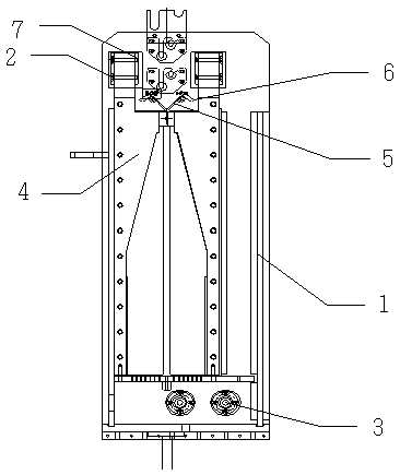
[0022] Such as figure 1 As shown in the figure, there is an corrosion-perforating device for improving the corrosion specific volume of aluminum foil. The aluminum foil is set on the roll body, including the corrosion tank 1, the foil clamping device and the heat dissipation device 2; the bottom of the corrosion tank 1 is provided with a liquid chamber 3, and the corrosion tank Two electrodes 4 are arranged symmetrically inside the body 1, an corrosive solution is arranged in the corrosion tank body 1, the foil clamping device is arranged above the corrosive liquid, the cooling device 2 is arranged above the foil clamping device, and a power supply is also included. Connect the roller body and the electrode. The pe...


PUM


Abstract

The invention discloses a corrosion hole forming device for improving the aluminum foil corrosion specific volume. An aluminum foil is arranged on a roller body, and comprises a corrosion groove body, a foil clamping device and a radiating device; a liquid cavity is formed in the bottom of the corrosion groove body, two electrodes are symmetrically arranged inside the corrosion groove body, and corrosion liquid is contained in the corrosion groove body; the foil clamping device is arranged above the corrosion liquid, and the radiating device is arranged above the foil clamping device; and a power supply source is further included and is electrically connected with the roller body and the electrodes. The hole forming device is high in hole forming efficiency and even in hole forming; the foil clamping device is arranged for preventing the aluminum foil from deflecting and preventing influences on homogeneity of hole forming on the two sides of the aluminum foil; and the radiating device is arranged, and therefore the temperature of the surface of the aluminum foil before the aluminum foil enters the corrosion liquid is reduced, the surface of the aluminum foil is prevented from going black, and the hole forming efficiency of the aluminum foil is prevented from being influenced.

Description

technical field [0001] The invention relates to a pore-forming device, in particular to a corrosion-forming device for increasing the corrosion specific volume of aluminum foil. Background technique [0002] Anode corrosion of aluminum foil is the first process of making medium and high voltage electrode foil. Its simple introduction is to vertically corrode many small honeycomb holes on the surface of the aluminum foil. The larger the inner surface area of ​​the holes, the better. The normal measurement is The size of the surface area is measured by how many UF per square centimeter. In order to obtain these small holes, the general processing technology is to treat the high-purity aluminum foil in the pre-treatment solution to remove the oil on the surface, and then in the mixed acid solution of sulfuric acid and hydrochloric acid. Holes are made in the medium, and then the holes are expanded in a dilute acid solution, and the acid solution and aluminum powder left inside ...

Claims


Application Information

Patent Timeline
Patent Type & Authority Patents(China)
IPC IPC(8): C25F3/04C25F7/00
CPCC25F3/04C25F7/00
Inventor 管德海
Owner 南通南辉电子材料股份有限公司
Learn More