Fume leakage preventing structure of integrated stove

An integrated stove, leak-proof technology, applied in the field of integrated stove, can solve the problems of body pollution, oil flow obstruction, cleaning, maintenance trouble, etc., and achieve the effect of solving oil leakage and simple structure

Active Publication Date: 2017-06-20
HUNAN XUNDA JI TUAN YOU XIAN GONG SI +1
View PDF8 Cites 4 Cited by
  • Summary
  • Abstract
  • Description
  • Claims
  • Application Information

AI Technical Summary

Problems solved by technology

The current oil fume exhaust system of the integrated cooker usually discharges the oily fume from the body to the public flue or outdoors through the suction chamber, fan, and chimney. There is an oil leakage hole at the bottom of the suction chamber and the chimney, and the chimney can usually choose to close one end and exhaust the smoke from the other end. When working, because the inside of the chimney is under positive pressure, the oil leakage hole of the chimney is relative to the inside of the machine body. It is completely open, and when the oil leaks, it will also discharge part of the oil fume. The oil fume diffuses and pollutes the inside of the integrated stove body, which brings many troubles to cleaning and maintenance.
Some chimneys are also equipped with a turnable smoke guide plate. The smoke guide plate is close to the four walls of the chimney to guide the flow of oil fumes, and divide the chimney into two areas: the working area and the waiting area, but the inside of the chimney is still under positive pressure. There will also be a certain amount of smoke, even if the oil leakage hole is opened in the waiting area for work, part of the oil fume will be discharged at the same time as the oil leaks, which will pollute the inside of the machine; Flow to the leak hole also creates an obstacle

Method used


Image

  • Fume leakage preventing structure of integrated stove
  • Fume leakage preventing structure of integrated stove
  • Fume leakage preventing structure of integrated stove

Examples


Embodiment 1

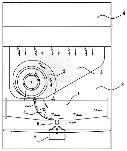
[0022] Embodiment one, such as figure 2 As shown, in the anti-leakage smoke structure of the integrated cooker of the present invention, the chimney 1 is a cuboid cavity, the upper end of the chimney 1 is connected to the air outlet of the fan 2, the bottom of the chimney 1 is provided with an oil leakage hole 6, and there is an oil collection box below the oil leakage hole 6 7. There is also an arc-shaped smoke guide plate 5 inside the chimney. The smoke guide plate 5 is close to the upper wall, front wall, and rear wall of the chimney 1 and guides the air outlet of the fan 2, separating the chimney 1 into the working area and the waiting area. In the two areas of the working area, a soot gap 9 is provided between the bottom end of the smoke guide plate 5 and the bottom wall of the chimney 1, and its height is 5-20mm. During work, the oily fume is inhaled from the smoke collecting hood 4, enters the chimney 1 through the smoke collecting chamber 3 and the fan 2, and is guide...

Embodiment 2

[0023] Embodiment 2. For the convenience of installation, the direction of smoke exhaust can be selected. The smoke guide plate 5 can be turned around its axis to support the replacement of the smoke exhaust port. The oil leakage hole 6 of the chimney 1 is set at the position below the smoke guide plate 5. In the direction of the axis of the smoke guide plate 5.

Embodiment 3

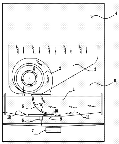
[0024] Embodiment three, such as image 3 As shown, the anti-leakage smoke structure of the integrated cooker of the present invention, compared with Embodiments 1 and 2, further includes a deflector 10, and the deflector 10 is located between the bottom end of the smoke guide 5 and the bottom wall of the chimney. above the oil fume gap 9, the deflector 10 is connected to the front wall and the rear wall of the chimney 1, the bottom end of the smoke deflector 5 is close to the deflector 10, and the smoke deflector 5 and the deflector 10 together The chimney 1 is divided into a positive pressure working area 11 and a negative pressure waiting area 12 , and the oil leakage hole 6 is located below the deflector 10 .


PUM


Abstract

The invention provides a fume leakage preventing structure of an integrated stove, and relates to an integrated stove. A chimney is connected with a fan, the bottom of the chimney is provided with oil leakage holes. An oil collection box is arranged below the oil leakage holes. A fume guide plate is installed in the chimney. The fume guide plate is tightly attached to the upper wall, the front wall and the rear wall of the chimney and guides an air outlet of the fan. An oily fume gap is arranged between the bottom end of the fume guide plate and the bottom wall of the chimney. When the fume leakage preventing structure works, the fume guide plate divides the chimney into a positive-pressure working area and a negative-pressure working area. The positive-pressure working area communicates with the negative-pressure working area through the oily fume gap, and the oil leakage holes are formed in the negative-pressure working area. According to the fume leakage preventing structure, the structure is simple, smooth oil drainage can be achieved, and internal cleanliness of the body of the integrated stove can be kept.

Description

technical field [0001] The invention relates to an integrated stove, in particular to an oil and smoke exhaust device for the integrated stove. Background technique [0002] The integrated stove is a combined stove that integrates multiple functions such as a range hood, a gas stove, a disinfection cabinet, and a storage cabinet. The current oil fume exhaust system of the integrated cooker usually discharges the oily fume from the body to the public flue or outdoors through the suction chamber, fan, and chimney. There is an oil leakage hole at the bottom of the suction chamber and the chimney, and the chimney can usually choose to close one end and exhaust the smoke from the other end. When working, because the inside of the chimney is under positive pressure, the oil leakage hole of the chimney is relative to the inside of the machine body. It is completely open, and part of the oil fume will be discharged when the oil leaks. The oil fume diffuses and pollutes the inside o...

Claims


Application Information

Patent Timeline
Patent Type & Authority Applications(China)
IPC IPC(8): F24C15/20
CPCF24C15/2042Y02B40/00
Inventor 伍斌强唐卫平刘葵郭聪颖郑志德徐根深伍奕
Owner HUNAN XUNDA JI TUAN YOU XIAN GONG SI
Why Eureka
Try Eureka